 +91 93730 08466
 Screen tubes and pipes
 Screen cylinders
 Flat panels and false bottoms
 Candle filter elements
 Water well screens
 Header and hub laterals
 Filter nozzles
 Resin traps
 Support grids
 Sieve bend (DSM) screens
 Centrifuge baskets
 Pressure screen baskets
 Screw press screens
 Rotary drum screens
 Passive intake screens
 Coanda intake screens
 Water and wastewater treatment
 Water wells and groundwater
 Sugar and distillery
 Brewing, malting and beverages
 Food processing
 Mining and minerals
 Oil, gas and petrochemicals
 Chemicals, fertilisers and pharma
 Power generation
 Pulp and paper
 Buildings and drainage
 Datasheet

Header lateral systems overview
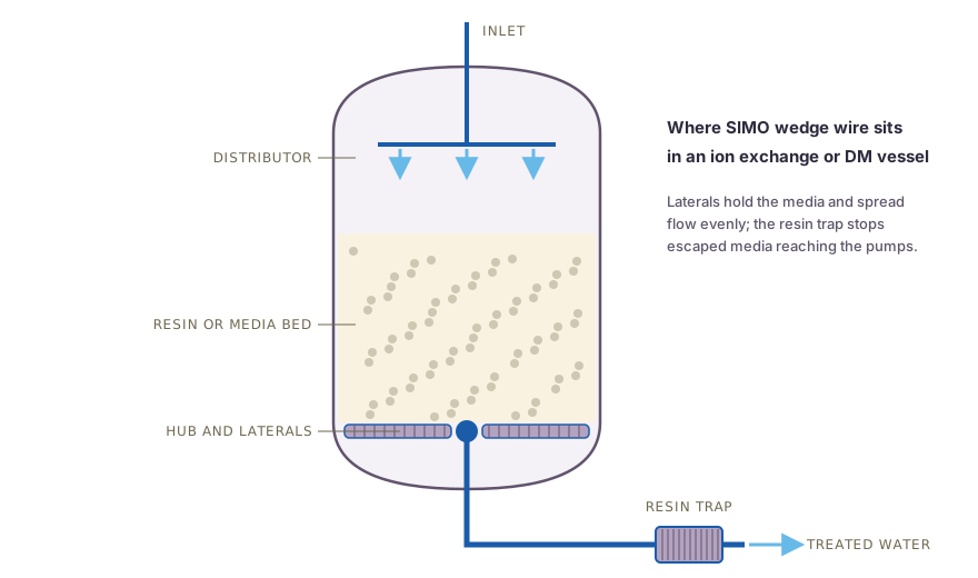
In an ion exchange or filter vessel, the internals decide how evenly the bed is used. Poor distribution leads to channelling, early breakthrough and wasted regenerant, while a cracked lateral releases resin or media into the treated water and on to the pumps.
SIMO Screens header lateral systems address both conditions. The lateral slots are sized so that the pressure drop across them governs the flow, which evens out distribution along each lateral and across the bed. The welded stainless laterals hold their slot width in service, so the resin or media stays in the vessel.
Features and benefits
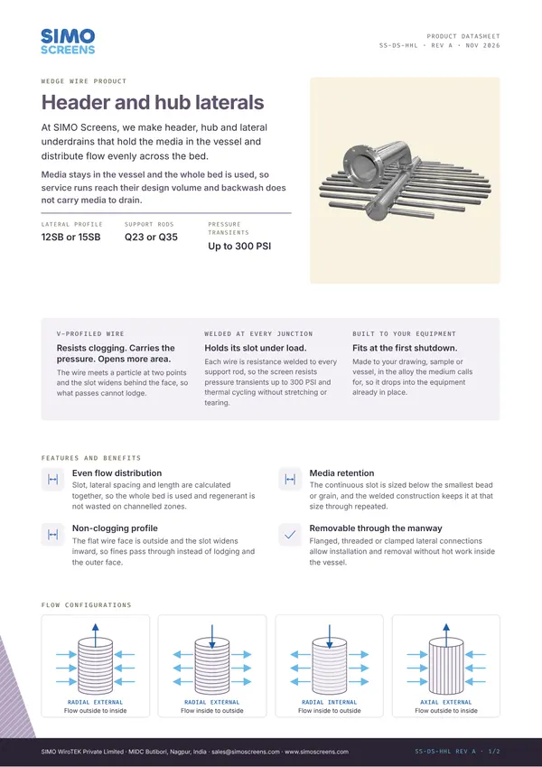
- Even flow distribution. Slot, lateral spacing and length are calculated together, so the whole bed is used and regenerant is not wasted on channelled zones.
- Media retention. The continuous slot is sized below the smallest bead or grain, and the welded construction keeps it at that size through repeated service and backwash cycles.
- Non-clogging profile. The flat wire face is outside and the slot widens inward, so fines pass through instead of lodging and the outer face stays clear.
- Removable through the manway. Flanged, threaded or clamped lateral connections allow installation and removal without hot work inside the vessel.
- Robust under transients. Welded stainless construction resists thermal cycling and pressure transients up to 300 PSI, such as those caused by backwash and valve operation.
Applications
- DM plant vessels: cation, anion and mixed bed units, as bottom collectors, upper distributors and middle collectors. See DM plant laterals.
- Condensate polishers in power plants. See condensate polishing internals.
- Softeners and boiler feed water treatment in sugar mills, breweries and process plants.
- Pressure sand, activated carbon and multigrade filters, as an alternative to a nozzle plate.
- Resin columns in chemical and pharmaceutical plants.
Swipe to see the full drawing.
Construction and specifications
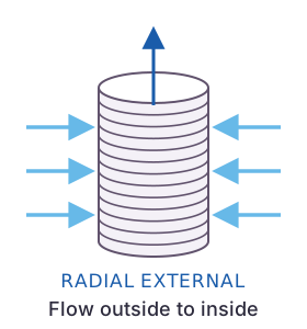
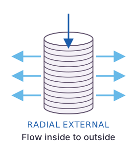
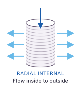
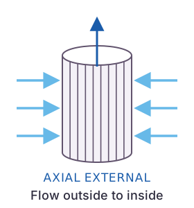
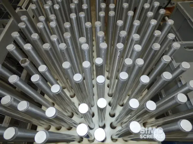
The header or hub is a pipe manifold connected to the vessel nozzle, with laterals branching from it at a set spacing. Each lateral is a wedge wire screen tube with the flat wire face outside. In service, water passes from the bed into the laterals, outside to inside; in backwash and regeneration the flow reverses and the laterals act as distributors.
Two layouts are built:
- Hub and lateral systems, with laterals radiating from a central hub, for round vessels with a central bottom or top nozzle.
- Headers and laterals, with laterals on both sides of a straight header, for larger vessels and retrofits.
For DM laterals, 12SB profile wire on Q23 rods suits low pressure and high flow, while 15SB is used for higher pressure at moderate flow. Supports tie the assembly to the vessel and take the backwash uplift.
| Parameter | SIMO range |
|---|---|
| Lateral slot opening | 25 microns (0.025 mm) to 25 mm |
| Slot tolerance | Plus or minus 5% of nominal, stated on the drawing |
| Lateral diameter | 25 mm to 800 mm |
| Lateral length | Up to 6,000 mm |
| Profile wire | 12SB on Q23 rods for low pressure and high flow; 15SB for higher pressure; others to design |
| Support rods | Q23, Q35, Q55, 35SB, F123, F203, F253, round 120, round 140 |
| Materials | SS 304, SS 316L, Duplex 2205, Super Duplex 2507, Hastelloy, Monel |
| Lateral connections | Flanged, threaded or clamped |
| Flow configuration | Radial, external profile, outside to inside, with reverse flow in backwash |
| Construction | Resistance welded at every wire and rod intersection; resists thermal cycling and pressure transients up to 300 PSI |
Swipe sideways to see the whole table.
Materials
SS 304 or SS 316L covers most water and condensate service, and the regenerant should be checked before the grade is fixed. Hydrochloric acid at regeneration strength attacks austenitic stainless steel, so vessels regenerated with HCl need a specific material review, and higher alloys such as Hastelloy C-276 may be recommended. The material selector gives a first comparison.
Engineering and quality
Lateral number, spacing, length and slot are designed from the vessel drawing, the service and backwash flows and the resin data, as set out in the header and lateral design guide. CFD is used for pressure drop prediction on custom designs, and FEA for structural validation. A resin trap on the outlet line completes the protection of downstream equipment.
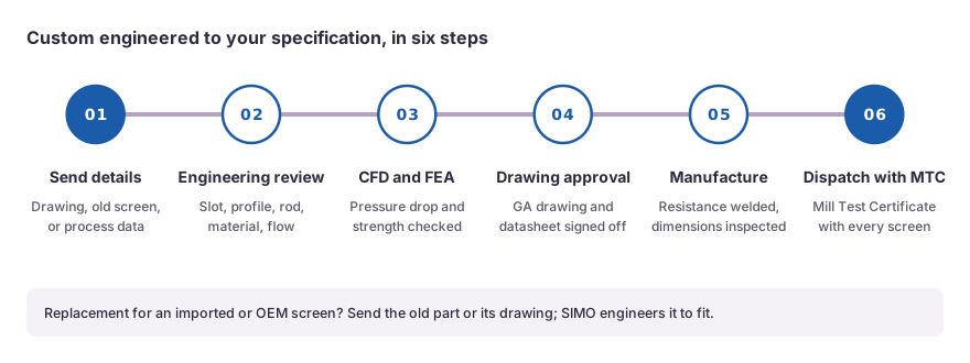
Slots are checked with feeler gauges at set-up, during the run and at the end of each lateral, and the final inspection report records the minimum, maximum and mean slot. Each lateral is identified with the job number, item and slot on a QR-coded tag, laser marked where the client requires it, and heat numbers are traceable from the Mill Test Certificate to the finished assembly. The MTC is standard, while the dimensional inspection report, QAP and pickling and passivation through an approved agency are available on request.
What to send for a quotation
- Vessel type (cation, anion, mixed bed, softener, polisher or filter) and service.
- Vessel drawing: diameter, height, nozzle positions and manway size.
- Position of the assembly: bottom collector, upper distributor or middle collector.
- Service and backwash flow rates.
- Resin or media type, with the data sheet showing the size range.
- Regenerant chemicals and concentrations.
- Operating pressure and temperature.
- Material grade, preferred lateral connection and the documents you require.
 Upload a drawing