 +91 93730 08466
 Screen tubes and pipes
 Screen cylinders
 Flat panels and false bottoms
 Candle filter elements
 Water well screens
 Header and hub laterals
 Filter nozzles
 Resin traps
 Support grids
 Sieve bend (DSM) screens
 Centrifuge baskets
 Pressure screen baskets
 Screw press screens
 Rotary drum screens
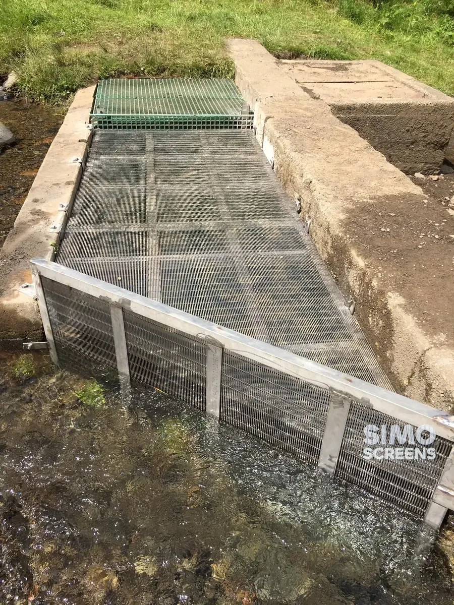
 Passive intake screens
 Coanda intake screens
 Water and wastewater treatment
 Water wells and groundwater
 Sugar and distillery
 Brewing, malting and beverages
 Food processing
 Mining and minerals
 Oil, gas and petrochemicals
 Chemicals, fertilisers and pharma
 Power generation
 Pulp and paper
 Buildings and drainage
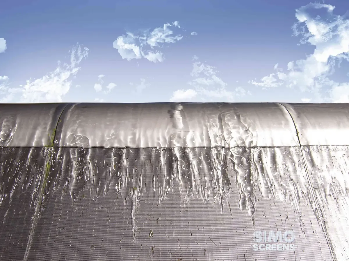
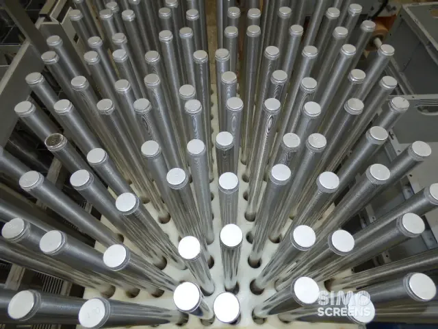

Power plant screening applications
SIMO Screens supplies wedge wire internals and screens for the water systems of thermal, captive and cogeneration power plants. Boiler feed water screens inside the DM plant and condensate polishers form part of the plant's water chemistry control, which protects the boiler and turbine, while intake and filter screens protect the cooling water circuit.
Resin that escapes into the feed water breaks down at boiler temperature and can release sulphate and chloride, which drive corrosion in the boiler and turbine. A cracked plastic lateral or a torn mesh element can start that sequence. Condensate polishers add their own loads, with high service flow and frequent resin transfer and regeneration, so weak laterals distort and uneven distribution channels the bed.
On the cooling water side, intakes and side-stream filters handle debris, silt and biological growth. A blinded intake starves the pumps, and a failed filter nozzle sends sand into the condenser circuit. Wedge wire meets these requirements with a welded stainless screen whose continuous slot retains resin and media and whose inward-widening shape resists blinding. The construction resists pressure transients up to 300 PSI.
Power plant water treatment screens, from intake to boiler
Raw water enters through the cooling water intake, where intake screens keep out debris and fish, and pretreatment filters use nozzles or laterals in their underdrains. The DM plant produces boiler feed water through cation, anion and mixed bed vessels, each fitted with hub and lateral internals. Condensate polishers treat the returning condensate before it goes back to the boiler, and resin traps on every outlet line capture escaped resin. Cooling water side-stream filters use nozzles to retain filter sand while part of the circulating flow is filtered.
Swipe to see the full drawing.
Equipment and screens for power plants
| Equipment | Screen function | SIMO product |
|---|---|---|
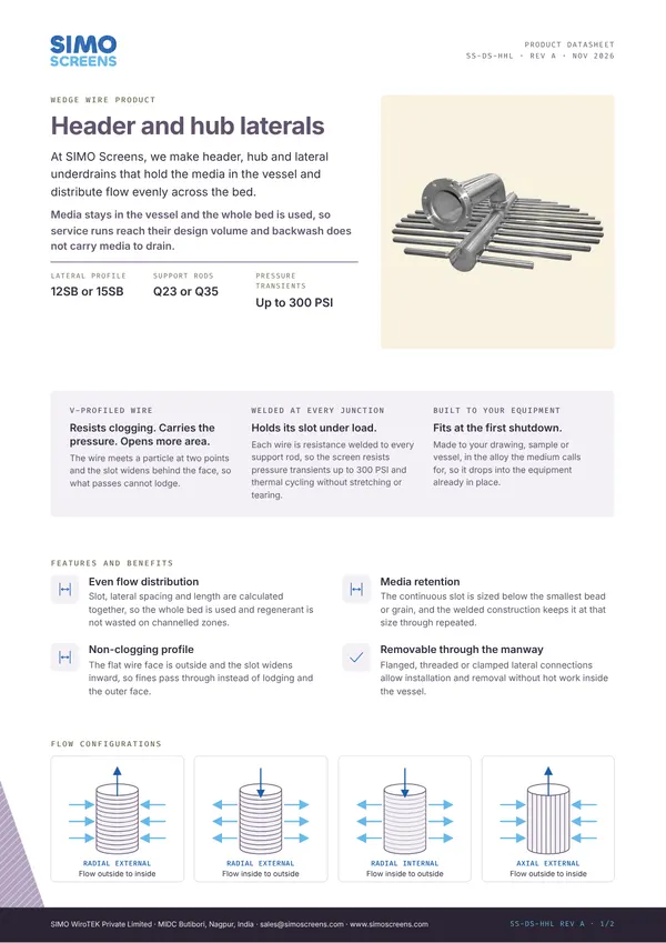
| Boiler feed water DM plant: cation, anion and mixed bed vessels | Distributes and collects flow and regenerant evenly while retaining resin | Header and hub lateral assemblies |
| Condensate polishers | Handles high service flow across the bed and holds back fine resin | Header and hub lateral assemblies |
| DM plant and polisher outlet lines | Captures escaped resin before it reaches pumps and the feed water line | Resin traps |
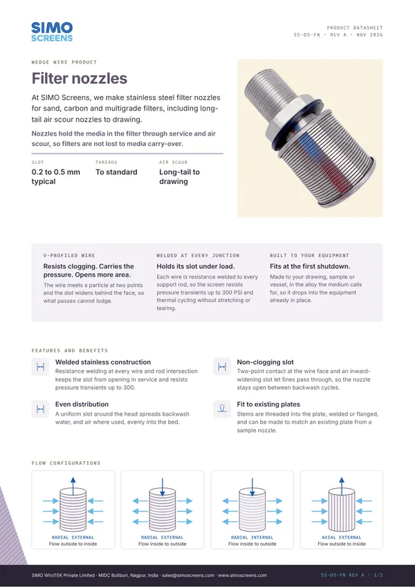
| Pretreatment and DM plant pressure filters | Retains filter media and spreads backwash flow in the underdrain | Filter nozzles |
| Cooling water intake | Keeps debris and fish out of the pump suction at low through-slot velocity | Intake screens |
| Cooling water side-stream filters | Retains filter sand while part of the circulating flow is filtered | Filter nozzles |
Swipe sideways to see the whole table.
Materials and design considerations
The points below reflect general engineering practice. The design for each plant is confirmed during engineering review.
Laterals and nozzles
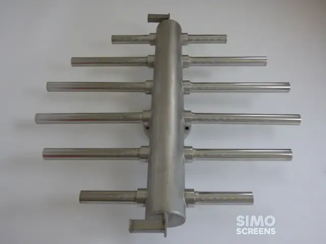
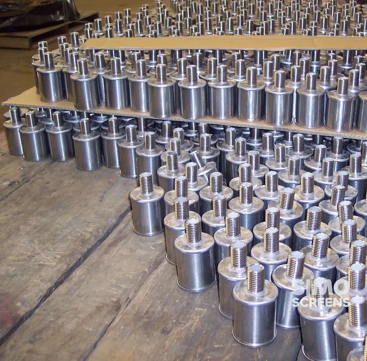
The slot is selected below the smallest resin bead or media grain. For DM plant laterals, 12SB profile wire on Q23 support rods is used for low pressure and high flow, and 15SB for higher pressure at moderate flow. Lateral length, spacing and open area are designed with the header so that every lateral carries a similar flow, as described in the header and lateral design guide.
Condensate polishers run hotter and at higher flow than a DM plant, and the internals must stay rigid under resin transfer surges. Custom designs are checked with CFD for flow balance and FEA for structure.
Resin traps
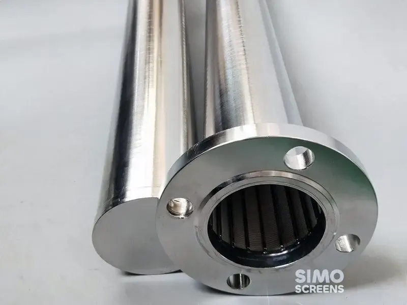
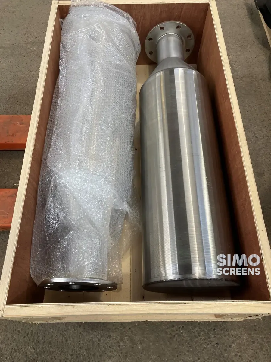
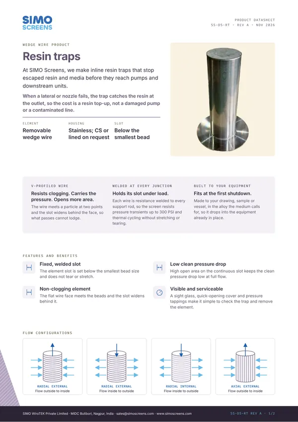
A resin trap is sized for the full line flow with a low clean pressure drop, and its slot matches the resin it protects against. A differential pressure gauge across the trap shows when it has captured resin. Resin trap housings in carbon steel or lined construction are supplied on request. The resin trap selection guide covers sizing.
Intakes
Intake screens are typically designed for a through-slot velocity of 0.15 m/s (0.5 ft/s) or less where fish protection matters, and a lower velocity also reduces the debris load and head loss. SIMO intake screens are made up to 800 mm in diameter.
Material
SS 304 and SS 316L cover most DM plant and polisher service, with SS 316L the usual choice where acid and caustic regenerants reach the internals. Seawater intakes and brackish cooling water generally call for Duplex 2205 or Super Duplex 2507.
SIMO Screens capability for power generation
Every internal is engineered to the vessel drawing and operating conditions, and the custom engineering process ends with a drawing approved before production. Existing laterals and nozzles can be replaced from a sample, a drawing or site measurements.
Profile wire is formed in house to SIMO profile codes and resistance welded to the support rods at every intersection. Slot width is checked with feeler gauges at set-up, during the run and at the end of each lateral or nozzle, against a standard tolerance of plus or minus 5 percent of nominal. Each item is identified with job number, item and slot on a QR-coded tag, laser marked where the client requires it, and heat numbers are traceable from the Mill Test Certificate to the finished screen.
The MTC is standard, and the dimensional inspection report, quality assurance plan and third-party inspection are provided on request. Production is at the SIMO works in MIDC Butibori, Nagpur, under an ISO 9001:2015 quality system.
What to send for a quotation
- Equipment: DM vessel, mixed bed, condensate polisher, pressure filter, side-stream filter or intake.
- Vessel drawing with diameter, nozzle positions, bottom shape and existing internals.
- Service flow, regeneration or backwash flow, design pressure and temperature.
- Resin grade or filter media size.
- For resin traps: line size, flow, pressure rating, end connections and housing material.
- For intakes: design flow, water depth, debris type and whether the water is fresh or seawater.
- Material specification and any documents you need beyond the standard MTC.
 Upload a drawing