 +91 93730 08466
 Screen tubes and pipes
 Screen cylinders
 Flat panels and false bottoms
 Candle filter elements
 Water well screens
 Header and hub laterals
 Filter nozzles
 Resin traps
 Support grids
 Sieve bend (DSM) screens
 Centrifuge baskets
 Pressure screen baskets
 Screw press screens
 Rotary drum screens
 Passive intake screens
 Coanda intake screens
 Water and wastewater treatment
 Water wells and groundwater
 Sugar and distillery
 Brewing, malting and beverages
 Food processing
 Mining and minerals
 Oil, gas and petrochemicals
 Chemicals, fertilisers and pharma
 Power generation
 Pulp and paper
 Buildings and drainage
 Datasheet

Architectural wedge wire panels overview
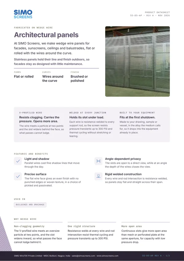
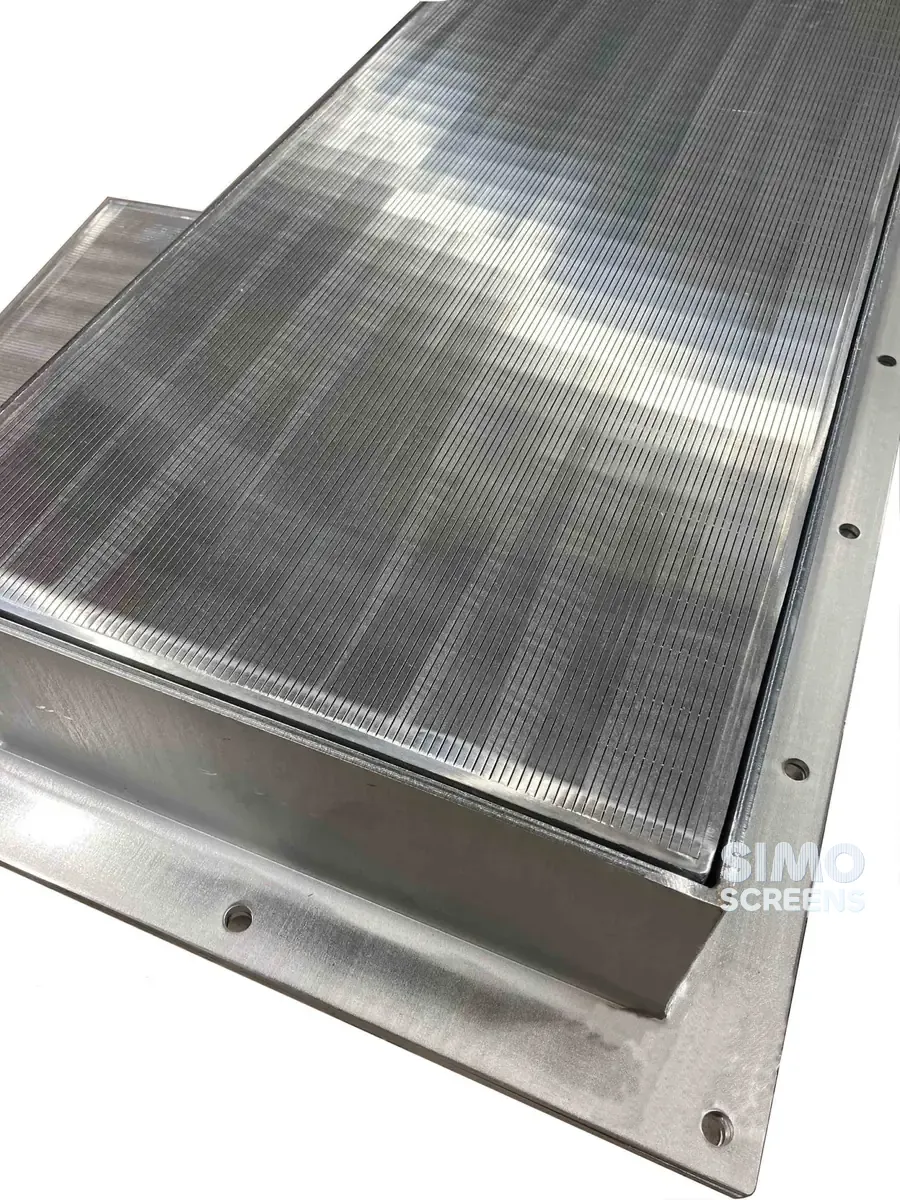
SIMO Screens architectural wedge wire panels are stainless screens of parallel V-profile wires, resistance welded to support rods and set in a perimeter frame. On a building, the wires read as fine, precise lines, and the panels are used wherever a facade, ceiling or screen needs texture, shading or partial transparency.
The character of a panel comes from three variables: the wire face width, the slot between wires and the depth of the wire. A change in any one alters the appearance, the light transmitted and the degree of privacy.
Features and benefits
- Light and shadow. Parallel wires cast fine shadow lines that move through the day, so a back-lit panel glows while a front-lit panel reads as a solid metallic face.
- Angle-dependent privacy. The slots are open to a direct view, while at an angle the depth of the wires closes the view, which screens a space without enclosing it.
- Precise surface. The flat wire face gives an even finish with no punched edges or woven texture, in a choice of pickled and passivated, brushed, bead blasted or electropolished finishes.
- Rigid welded construction. Every wire and rod intersection is resistance welded, so panels stay flat and straight across their span.
- Low maintenance. Stainless steel needs no painting, and the open slots allow rain to wash the surface.
Applications
- Facades and cladding, where a wedge wire facade forms a rain screen or a veil over glazing or blockwork
- Sunscreens and louvres, which cut glare and heat gain while keeping a view out
- Ceilings and soffits in lobbies, canopies and covered walkways
- Balustrade infill for stairs, balconies and atriums
- Construction screens and partitions for plant rooms, car park facades and service yard enclosures
- Feature elements such as column cladding, signage backgrounds and lighting diffusers
The wider range for buildings is described under buildings, architecture and drainage.
Construction and specifications
| Item | Options |
|---|---|
| Slot | Narrow slots for privacy and safety, wide slots for transparency |
| Profile wire | Fine profiles such as 12SB for a delicate line, heavy profiles such as 56SB for a bold one |
| Support rod | Profile, flat or round rods, set behind the face |
| Wire direction | Vertical, horizontal or diagonal in the frame |
| Form | Flat, segmented, or rolled to a radius with the wires around the curve |
| Panel size | Single panels up to 2,400 mm wide and 4,000 mm long |
| Material | SS 304 or SS 316L |
| Frame and fixings | Perimeter frames, brackets, clips and concealed fixings, supplied with the panels |
| Finish | Brushed or bead blasted; pickled and passivated or electropolished through approved agencies |
Swipe sideways to see the whole table.
Design considerations
Appearance and open area. For a given slot, a wider wire gives a denser appearance, and the open area calculator compares options before samples are made.
Panel size and span. Larger panels need deeper support rods or intermediate supports to stay flat, so the module size and support points are fixed early in the design.
Wind and impact loads. Facade and balustrade panels must suit the loads in the applicable building code. The project's structural engineer confirms the design loads, and the panel and its fixings are designed to them.
Environment. SS 316L is selected near the coast, in polluted air and close to pools, as explained in the material selection guide.
Interfaces. Frames and fixings are detailed from drawings that show how each panel meets glazing, slabs and adjoining cladding.
Engineering and quality
Each design is reviewed for slot, span and fixing loads before production, and fabrication welds on frames are visually inspected. Slots are checked with feeler gauges during production to a standard tolerance of plus or minus 5 percent of nominal. Every order is supplied with a Mill Test Certificate, and a dimensional inspection report is available on request.
What to send for a quotation
- Application: facade, sunscreen, ceiling, balustrade or screen
- Elevations or drawings with panel module sizes
- The appearance required: wire face width, slot, or a reference image
- Wire direction and any curved areas, with the radius
- Support points and the preferred fixing method
- Design loads from your structural engineer
- Material and finish
- Quantity and delivery location
 Upload a drawing