 +91 93730 08466
 Screen tubes and pipes
 Screen cylinders
 Flat panels and false bottoms
 Candle filter elements
 Water well screens
 Header and hub laterals
 Filter nozzles
 Resin traps
 Support grids
 Sieve bend (DSM) screens
 Centrifuge baskets
 Pressure screen baskets
 Screw press screens
 Rotary drum screens
 Passive intake screens
 Coanda intake screens
 Water and wastewater treatment
 Water wells and groundwater
 Sugar and distillery
 Brewing, malting and beverages
 Food processing
 Mining and minerals
 Oil, gas and petrochemicals
 Chemicals, fertilisers and pharma
 Power generation
 Pulp and paper
 Buildings and drainage

Reactor support grid overview
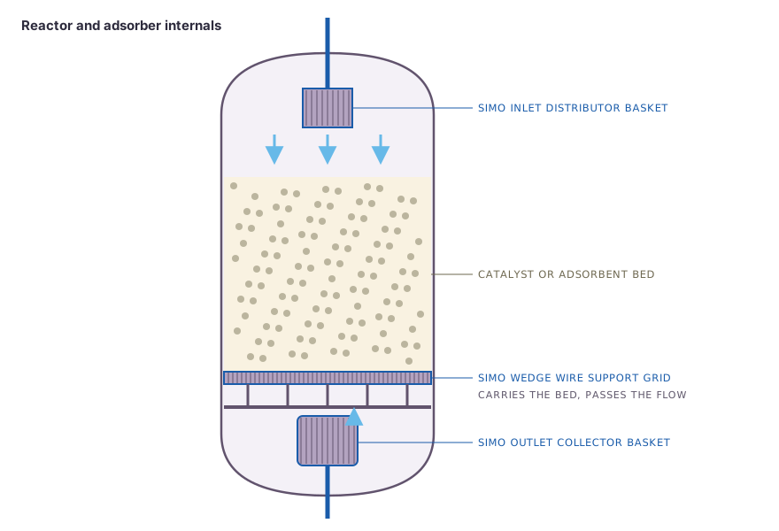
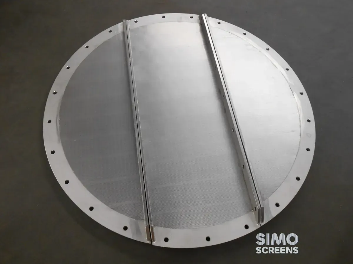
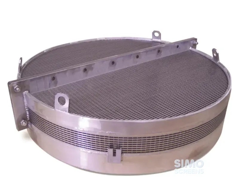
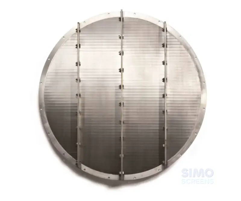
Hydrotreaters, hydrocrackers and other fixed bed reactors hold catalyst in one or more beds. Each bed rests on a reactor support grid, often with a layer of inert ceramic balls on top, and process fluid passes down through the bed and the grid to the quench zone or the next bed. At the bottom, an outlet collector keeps catalyst and balls out of the outlet nozzle, while at the top an inlet distributor basket spreads the feed. Radial flow reactors use centre pipes, and molecular sieve driers and adsorbers use the same family of internals.
Grid problems show as rising pressure drop or as catalyst found downstream. Layered mesh over a bar grating tears at seams and edges, weak grids sag under bed weight and pressure drop so that gaps open at the shell ring, and start-ups, shutdowns and regeneration crack rigid joints. Fines and coke also close mesh openings, which shortens run length and can force an unplanned shutdown.
Swipe to see the full drawing.
Design considerations for a catalyst bed support
Slot. The slot sits below the smallest particle on the grid, with a margin. This is usually the smallest support ball layer, or the catalyst itself where no balls are used. A larger slot lowers pressure drop, so the slot is sized as open as the particles allow.
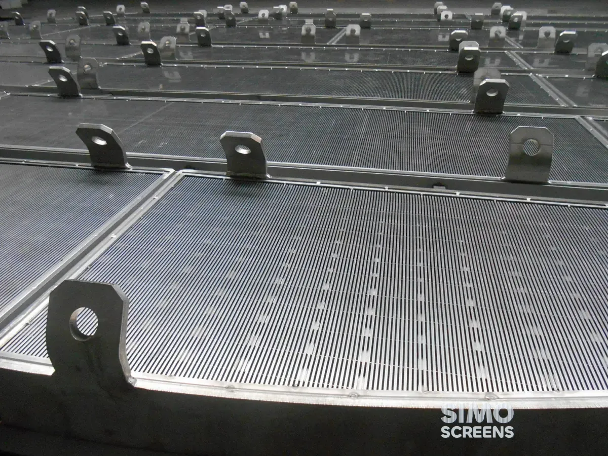
Profile and open area. The flat face of the V-profile wire carries the bed, and the slot widens below so that fines pass instead of lodging. Open area (%) = Slot x 100 / (Slot + Wire width). A 2 mm slot on 42SB wire, 3.3 mm wide, gives about 38 percent open area, and a 1 mm slot on 55SB, 5 mm wide, about 17 percent.
Load. Grids carry heavy beds, so heavy profiles such as 42SB, 55SB or 56SB on F203 or F253 bars are typical. Beam spacing and bar height are set by FEA for bed weight, pressure drop and temperature, and CFD is used to predict pressure drop on custom designs.
Thermal cycling and pressure. The welded construction resists thermal cycling and pressure transients up to 300 PSI. Segment joints and fixings are detailed to allow thermal movement at start-up, shutdown and regeneration.
Sealing. A seal arrangement between the grid segments and the reactor shell ring prevents catalyst bypass at the edge, which is a common point of migration on older internals.
Construction and options
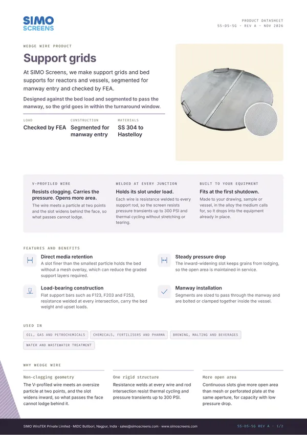
SIMO profile wire is formed in house and resistance welded to support bars at every intersection, with seam welding where the design calls for it. Grids are flat segmented wedge wire panels on support beams, and each segment is sized to pass the manway and bolts to its neighbours and to the shell ring. Brackets, clamps, seal details and edge details are fabricated with the grid.
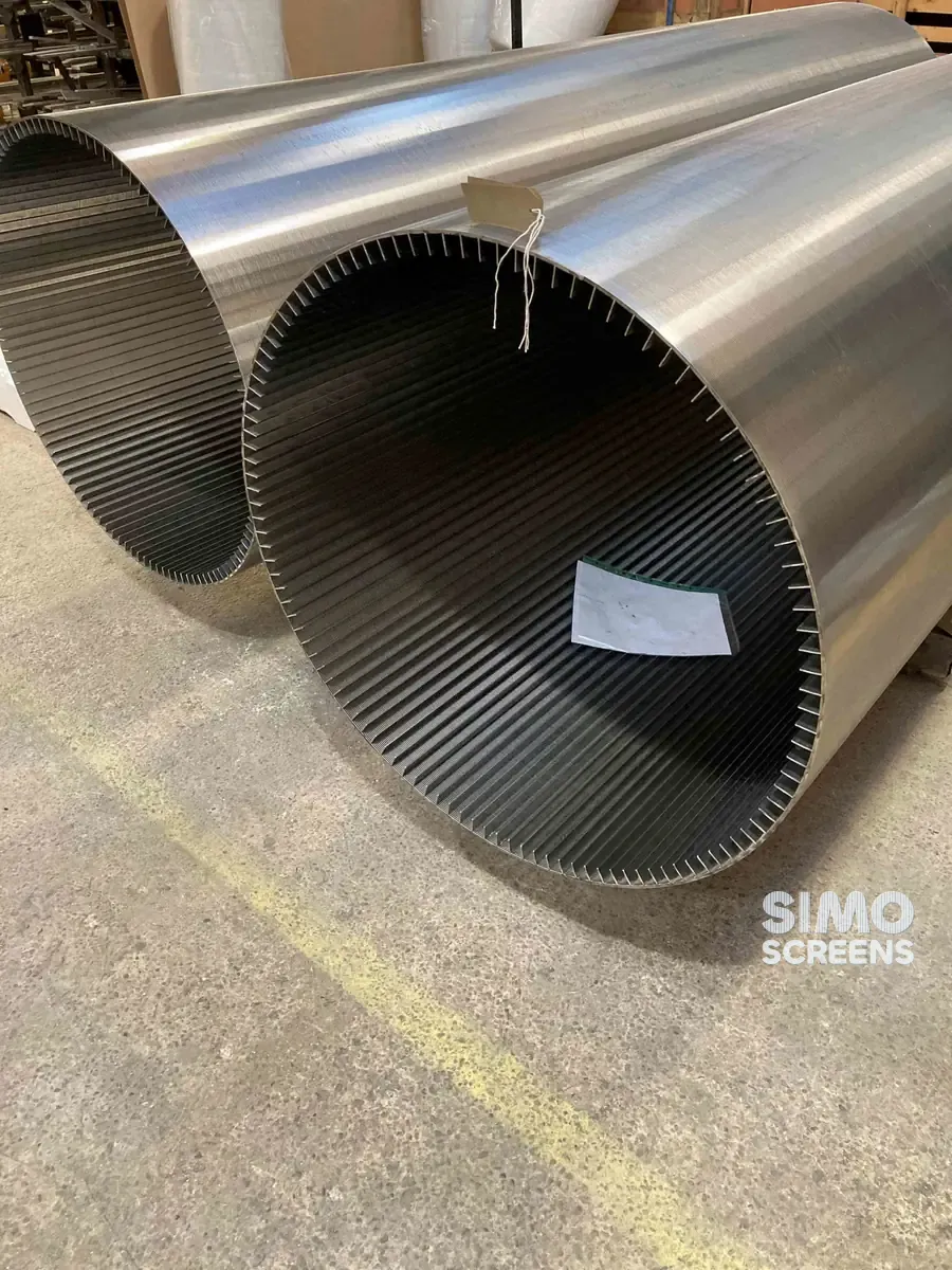
Outlet collectors are cylindrical or domed wedge wire baskets over the outlet nozzle, with flow from outside to inside. Inlet distributor baskets and radial flow centre pipes are built from wedge wire cylinders with flanged or welded ends.
| Item | SIMO range or typical value |
|---|---|
| Items | Support grids, outlet collectors, inlet distributor baskets, centre pipes |
| Slot opening | 25 microns (0.025 mm) to 25 mm, below the smallest particle |
| Slot tolerance | Plus or minus 5% of nominal, stated on the drawing |
| Profile wire | 42SB, 55SB, 56SB |
| Support bars | F203, F253 |
| Cylinder size | Diameter 25 to 800 mm, length up to 6,000 mm |
| Pressure | Welded construction resists pressure transients up to 300 PSI |
| Design | FEA for structure, CFD for pressure drop |
Swipe sideways to see the whole table.
Fabrication welds are visually inspected, and dye penetrant testing is carried out wherever specified. Each item carries a QR-coded tag with job number, item and slot, and is laser marked as well where the client requires it.
Materials
Reactor internals are built in SS 304, SS 316L, Duplex 2205, Super Duplex 2507, Hastelloy C-276 and Monel, and stabilised austenitic grades such as SS 321 or SS 347 are supplied when a licensor specifies them. The choice follows the process fluid, the temperature and the licensor's specification. The Mill Test Certificate is supplied as standard, with heat numbers traceable to the finished item, and a dimensional inspection report, QAP and PMI through an approved agency are available on request. See the material selection guide.
Replacement and retrofit
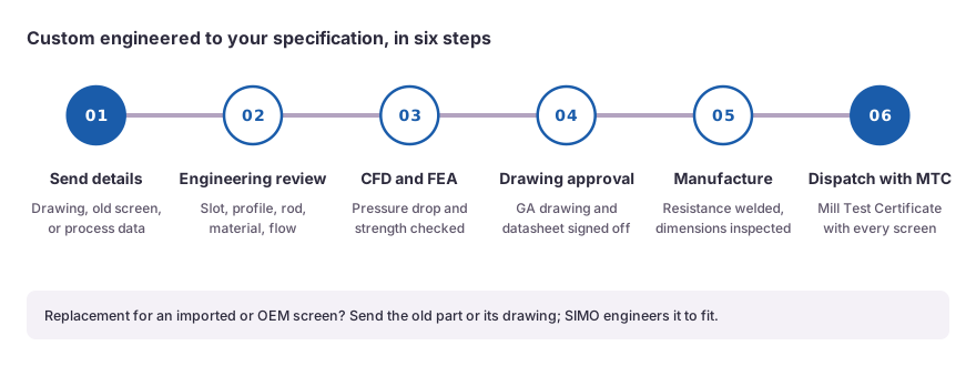
Most internals are changed at a planned turnaround, and existing reactor internals, including imported and OEM items, are replaced from a sample or a drawing. The reactor drawing and the existing internals drawing should be shared well ahead, so that drawing approval and manufacture are complete before the shutdown.
The support ring and beam seats should be measured at the previous opening where possible. Out-of-round shells and worn seats are easier to allow for at the drawing stage. Our support grids and outlet baskets and collectors pages give the product range, and the material selector helps shortlist grades.
What to send for a quotation
- Reactor inside diameter, design pressure and design temperature.
- Support ring and beam details, with the reactor drawing.
- Manway size and position.
- Bed weight and design pressure drop across the grid.
- Particle sizes, especially the smallest particle on the grid.
- Process fluid, contaminants and the specified material.
- Regeneration and start-up cycles.
- Existing internals drawing and turnaround date.

 Upload a drawing