 +91 93730 08466
 Screen tubes and pipes
 Screen cylinders
 Flat panels and false bottoms
 Candle filter elements
 Water well screens
 Header and hub laterals
 Filter nozzles
 Resin traps
 Support grids
 Sieve bend (DSM) screens
 Centrifuge baskets
 Pressure screen baskets
 Screw press screens
 Rotary drum screens
 Passive intake screens
 Coanda intake screens
 Water and wastewater treatment
 Water wells and groundwater
 Sugar and distillery
 Brewing, malting and beverages
 Food processing
 Mining and minerals
 Oil, gas and petrochemicals
 Chemicals, fertilisers and pharma
 Power generation
 Pulp and paper
 Buildings and drainage
Design basis
SIMO Screens designs each custom screen from the process it serves. The design basis records the media or particle size to retain, flow rate, allowable pressure drop, operating and upset pressure, temperature, chemistry, cleaning method and the space available, and each of these values governs a later design decision.
Slot and open area
The slot is set by what must be retained. For media retention it is sized below the smallest grain to be held, and for dewatering or sizing it is set at the required cut point. Open area then follows from slot and wire width:
Open area (%) = Slot x 100 / (Slot + Wire width)
Greater open area reduces through-slot velocity and pressure drop, but a narrower wire carries less load, so the two are balanced for each application. The trade-off is set out in the slot and open area guide.
Profile wire and support rod
Wedge wire screen technology relies on the V-profile, whose slot widens inward so that particles pass through or remain on the surface. Light profiles suit fine slots and low loads, while heavy duty profiles suit abrasive slurries, centrifugal load and long service.
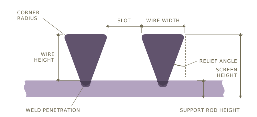
Swipe to see the full drawing.
The support rod carries the screen across its span, and its height and spacing set stiffness, collapse resistance and unsupported length. Tall flat rods suit support grids and false bottoms, while profile and round rods suit cylinders and fine elements.
Flow configuration
The flat face of the wire must meet the process stream, so the wire is placed outside or inside the support rods according to the direction of flow.
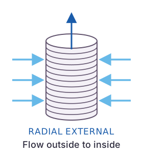
Four configurations are built: radial external outside to inside, radial external inside to outside, radial internal inside to outside, and axial external outside to inside. Each is described in the flow configuration guide.
Material selection
The alloy is matched to fluid, temperature and chloride level. SS 304 suits most fresh water and SS 316L suits food, brewing and general chemical service, while Duplex 2205, Super Duplex 2507, Hastelloy and Monel cover higher chlorides, seawater and aggressive chemicals. Strength and cost are also weighed, since a stronger alloy can allow a lighter section, and the material selector gives a first indication.
CFD for pressure drop
Computational fluid dynamics models flow through and around the screen to predict pressure drop and confirm even distribution. It is applied chiefly to header and lateral systems, intake screens and outlet collectors, where uneven flow causes channelling in a resin bed, high local velocity at an intake or early wear.
FEA for structural validation
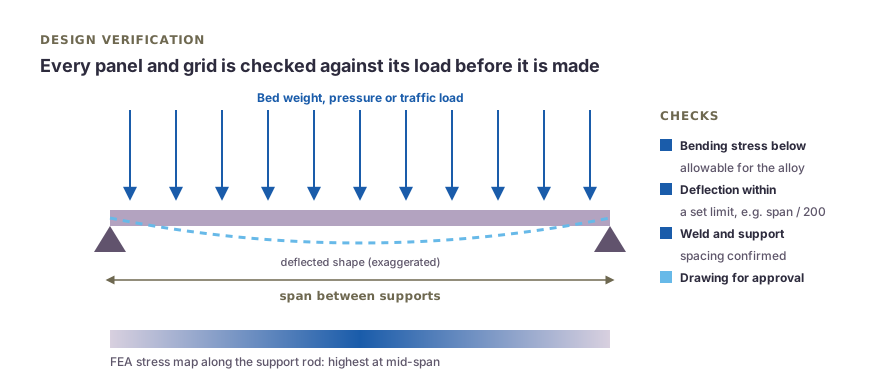
Swipe to see the full drawing.
Finite element analysis confirms that the screen carries its load without excessive deflection or failure, covering collapse pressure on cylinders, bed weight on support grids and centrifugal load on baskets. Every wire and rod intersection is resistance welded, and the construction resists thermal cycling and pressure transients up to 300 PSI.
Seven-point design review
Each custom design passes the same seven checks, and the result of each is recorded against the drawing.
- Process data. Particle or media size, flow, allowable pressure drop, operating and upset pressure, temperature, chemistry and cleaning, with any gaps raised with the customer.
- Slot and open area. Slot against the size to retain, with a margin, and open area from slot and wire width.
- Velocity. Through-slot or entrance velocity against the limit for the application, based on the open area expected to remain clear in service.
- Structural check. Collapse pressure, bed load, span, centrifugal load or thermal expansion, by calculation or FEA.
- Material. Grade against chlorides, temperature, pH and cleaning chemicals, and the strength the section requires.
- Fabrication details. End connections, flanges, segment joints, manway passage, tolerances and finish.
- Drawing for approval. A general arrangement drawing with slot, wire, rod, material and key dimensions, issued for approval before manufacture.
Worked example: tube well screen
| Step | Typical figure |
|---|---|
| Design flow | 36 m³/h (0.01 m³/s) from a gravel packed tube well |
| Screen | 200 mm diameter, 1.0 mm slot, 28SB wire (2.2 mm wide) |
| Open area | 1.0 x 100 / (1.0 + 2.2) = 31.25% |
| Open area per metre | π x 0.2 x 0.3125 = 0.196 m² |
| Entrance velocity limit | About 0.03 m/s, a commonly used design limit |
| Open area required | 0.01 / 0.03 = 0.333 m² |
| Length, clean screen | 0.333 / 0.196 = 1.7 m |
| Length, effective open area 50% of calculated | About 3.4 m |
Swipe sideways to see the whole table.
Effective open area is normally taken as about 50 percent of the calculated value, or to the client's own design factor. The structural check then sets the rod and wire for the well depth, and the method for each product type is given in the screen design calculations guide.
Replacement of imported and OEM screens
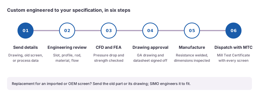
Replacement screens are designed from a sample, an existing drawing or site measurements. Interfaces, slot, wire, rod and material are recorded, the original design is checked against the operating conditions, and a drawing is issued for approval as for any new design. The full method is described under custom engineering.
 Upload a drawing