 +91 93730 08466
 Screen tubes and pipes
 Screen cylinders
 Flat panels and false bottoms
 Candle filter elements
 Water well screens
 Header and hub laterals
 Filter nozzles
 Resin traps
 Support grids
 Sieve bend (DSM) screens
 Centrifuge baskets
 Pressure screen baskets
 Screw press screens
 Rotary drum screens
 Passive intake screens
 Coanda intake screens
 Water and wastewater treatment
 Water wells and groundwater
 Sugar and distillery
 Brewing, malting and beverages
 Food processing
 Mining and minerals
 Oil, gas and petrochemicals
 Chemicals, fertilisers and pharma
 Power generation
 Pulp and paper
 Buildings and drainage
Wedge wire slot size and open area in screen performance
Most screen problems trace back to two numbers. A slot that is too large loses media or product, while a slot that is too fine, or an open area that is too low, blinds early and raises pressure drop.
Wedge wire allows the two numbers to be set independently. The slot is chosen for retention, and the wire width is chosen to give the required open area at that slot, within the strength and wear limits of the application.
What the slot is
The slot is the clear gap between two adjacent profile wires, measured at the screen face. The face is the flat head of the V-profile, on the side that meets the feed.
Because the profile is a V, the gap widens behind the face. A particle that passes the face has a clear path through the screen, while a particle that is too large rests on two points at the face without wedging in. The slot is therefore stated as a single width in microns or millimetres, which is the narrowest point of the opening and is set directly by the winding pitch.
Slot selection by application
Slot selection starts from the solids to be retained or passed, and the basis depends on the application.
| Application | Basis for the slot | Typical approach |
|---|---|---|
| Media retention (resin, sand, carbon, catalyst) | Smallest particle in the bed | Slot smaller than the smallest grain or bead, with a margin |
| Water well screens | Sieve analysis of the formation or gravel pack | Slot that retains the required fraction of the pack or formation |
| Dewatering and drainage | Product size and the fines acceptable in the filtrate | Largest slot that keeps product losses acceptable |
| Sizing and classification | Required cut size | Slot set to the cut, adjusted for the screen type |
| Intake and fish screens | Debris and fish protection criteria | Slot set by the regulator or owner, then sized for velocity |
Swipe sideways to see the whole table.
On a sieve bend the separation size is smaller than the slot, because the edge of each wire slices a thin layer off the flowing slurry. Sieve bends are therefore sized by the required cut rather than by the slot alone.
Specifications written in mesh are converted with the mesh to micron guide, which relates sieve numbers to slot width.
The wedge wire open area formula
For a wedge wire surface with parallel slots, open area is:
Open area (%) = Slot x 100 / (Slot + Wire width)
Both values are in the same unit. The wire width is the head width of the profile wire, which is the dimension at the screen face, and not its height.
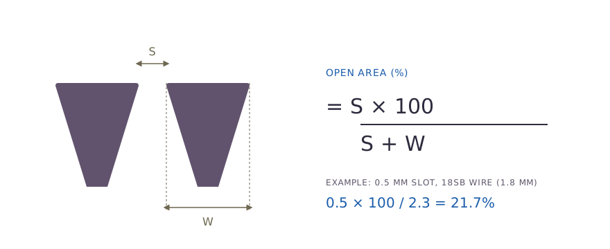
Swipe to see the full drawing.
The formula shows the influence of wire width. At fine slots the wire occupies most of the surface, so halving the wire width can nearly double the open area.
Worked open area table for SIMO profile wires
The table applies the formula to the SIMO standard profile wire widths. Values are nominal open area in percent, rounded to one decimal place.
| Profile wire | Wire width (mm) | 0.1 mm slot | 0.25 mm slot | 0.5 mm slot | 1.0 mm slot | 2.0 mm slot | 5.0 mm slot |
|---|---|---|---|---|---|---|---|
| 12SB | 1.0 | 9.1 | 20.0 | 33.3 | 50.0 | 66.7 | 83.3 |
| 15SB | 1.52 | 6.2 | 14.1 | 24.8 | 39.7 | 56.8 | 76.7 |
| 18SB | 1.8 | 5.3 | 12.2 | 21.7 | 35.7 | 52.6 | 73.5 |
| 28SB | 2.2 | 4.3 | 10.2 | 18.5 | 31.2 | 47.6 | 69.4 |
| 35SSB | 2.6 | 3.7 | 8.8 | 16.1 | 27.8 | 43.5 | 65.8 |
| 35SB | 3.0 | 3.2 | 7.7 | 14.3 | 25.0 | 40.0 | 62.5 |
| 42SB | 3.3 | 2.9 | 7.0 | 13.2 | 23.3 | 37.7 | 60.2 |
| 55SB and 56SB | 5.0 | 2.0 | 4.8 | 9.1 | 16.7 | 28.6 | 50.0 |
Swipe sideways to see the whole table.
Two patterns are clear. Open area rises steeply with slot at fine sizes, and at any slot a lighter wire gives more open area but less strength and wear allowance.
Worked example 1: open area for a fine slot
A filter element needs a 0.25 mm slot, and the candidate wires are 15SB (1.52 mm wide) and 18SB (1.8 mm wide).
- 15SB: 0.25 x 100 / (0.25 + 1.52) = 25 / 1.77 = 14.1 percent
- 18SB: 0.25 x 100 / (0.25 + 1.8) = 25 / 2.05 = 12.2 percent
The lighter wire gives about 16 percent more open area. If the element sees modest differential pressure, 15SB is the better hydraulic choice; if it sees abrasion or high load, the additional metal in 18SB is usually worth the lower open area.
Worked example 2: through-slot velocity on a cylinder
A screen cylinder has an outside diameter of 200 mm and a screened length of 2 m, with a 0.5 mm slot on 18SB wire, and it passes 100 m³/h.
- Screen surface area = π x 0.2 x 2 = 1.257 m²
- Open area = 0.5 x 100 / (0.5 + 1.8) = 21.7 percent
- Open flow area = 1.257 x 0.217 = 0.273 m²
- Flow = 100 / 3,600 = 0.0278 m³/s
- Average through-slot velocity = 0.0278 / 0.273 = 0.10 m/s
This is an average value. Flow is rarely uniform along a screen, so you should also check the velocity near the outlet end, where it is usually highest.
Worked example 3: sizing an intake for velocity
Fish-protection intake screens are typically designed for a through-slot velocity of 0.15 m/s (0.5 ft/s) or less. Take an intake that must pass 0.5 m³/s with a 3 mm slot on 42SB wire (3.3 mm wide).
- Open area = 3 x 100 / (3 + 3.3) = 47.6 percent
- Open flow area needed = 0.5 / 0.15 = 3.33 m²
- Gross screen surface needed = 3.33 / 0.476 = 7.0 m²
An allowance for debris loading and uneven flow is then added to the gross area. The intake screen calculator runs this sizing for any flow, slot and wire.
Nominal and effective open area
The formula gives nominal open area at the slot face. The effective area in service is lower, for three reasons:
- support rods sit behind the slot and shadow part of it;
- unslotted lengths such as end rings, blank ends and frames carry no flow;
- the bed, formation, gravel pack or solids cover part of the face.
For water well screens, effective open area is commonly taken as about 50 percent of the calculated open area, or to the design factor set by the client or consultant. For media retention screens, the bed in contact with the face reduces the area that actually carries flow, and this allowance is made before velocity limits are set.
Slot accuracy and inspection
A nominal slot has little value if it varies along the screen, because one wide gap passes media that the rest of the screen retains. On wedge wire the slot is set by the winding pitch, which equals wire width plus slot, so pitch control is the basis of slot accuracy.
SIMO checks the slot with feeler gauges at welding set-up, during the run and at the end of each screen, and uses optical measurement where a physical gauge cannot be used. The standard tolerance is plus or minus 5 percent of nominal, stated on the drawing, and the final inspection report records the minimum, maximum and mean slot. A Mill Test Certificate is supplied with every product.
Design trade-offs
| Design objective | Change | Consequence |
|---|---|---|
| More open area at the same slot | Use a narrower profile wire | Less strength and less wear allowance |
| Finer retention | Use a smaller slot | Lower open area, higher velocity and pressure drop |
| Lower through-slot velocity | Add screen surface or open area | Larger or longer screen |
| Longer life in abrasive service | Use a wider, taller wire | Lower open area |
Swipe sideways to see the whole table.
Profile choice is covered in detail in the profile wire and support rod guide.
Related products, tools and engineering support
- Products: water well screens, intake screens, header and lateral assemblies and filter nozzles are all sized from this slot and open area calculation.
- Tool: the open area calculator applies the formula for any slot and wire width.
- Engineering: for a screen sized to a given flow, velocity and pressure drop, see custom engineering. SIMO uses CFD for pressure drop prediction on custom designs.