 +91 93730 08466
 Screen tubes and pipes
 Screen cylinders
 Flat panels and false bottoms
 Candle filter elements
 Water well screens
 Header and hub laterals
 Filter nozzles
 Resin traps
 Support grids
 Sieve bend (DSM) screens
 Centrifuge baskets
 Pressure screen baskets
 Screw press screens
 Rotary drum screens
 Passive intake screens
 Coanda intake screens
 Water and wastewater treatment
 Water wells and groundwater
 Sugar and distillery
 Brewing, malting and beverages
 Food processing
 Mining and minerals
 Oil, gas and petrochemicals
 Chemicals, fertilisers and pharma
 Power generation
 Pulp and paper
 Buildings and drainage
Underdrain design functions
The underdrain of an ion exchange vessel or pressure filter is hidden from view until it fails. A broken lateral loses resin to the service line, and a poorly distributed underdrain leaves dead zones, so that part of the bed is never properly regenerated or backwashed.
An underdrain performs three functions. It retains the media, collects the service flow evenly across the vessel floor, and distributes backwash or regenerant evenly in the reverse direction.
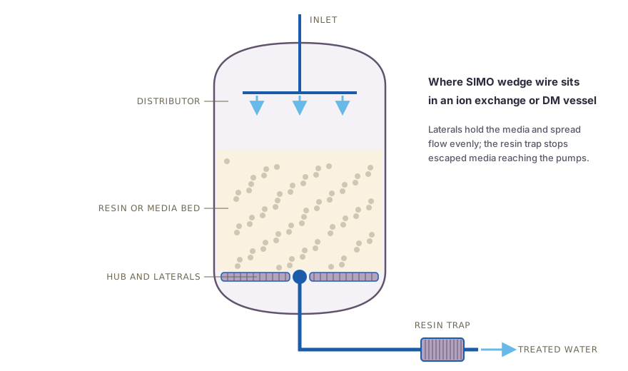
Swipe to see the full drawing.
Header or hub layout
| Feature | Header lateral | Hub lateral |
|---|---|---|
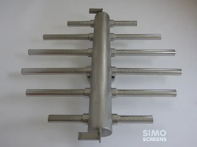
| Layout | Straight header across the vessel, laterals branching from both sides | Central hub, laterals radiating outward |
| Typical vessel | Larger diameters, flat or concrete-filled bottoms | Smaller diameters, dished heads |
| Lateral lengths | Vary with position, longest at the centre | All equal |
| Area coverage | Even, set by the lateral pitch along the header | Laterals spread apart towards the wall |
| Entry | Header passes through the shell or connects to a bottom nozzle | Hub connects to a central bottom nozzle |
Swipe sideways to see the whole table.
Header lateral systems
The header runs along a diameter, with laterals branching at right angles at a fixed pitch on both sides. Each lateral extends to near the shell, so the lateral lengths follow the vessel chord at each position. Coverage is even because every lateral at a given pitch serves a strip of similar width, which makes header systems the usual choice for larger vessels.
Hub lateral systems
A hub sits at the centre of the vessel bottom, with laterals radiating from it at equal angles. All laterals are the same length, which simplifies manufacture and spares.
The gap between laterals grows with radius: with n laterals, the spacing at radius r is 2 x π x r / n. Near the wall each lateral therefore serves a much wider band than near the hub, which designers balance with short intermediate laterals or adjusted slot lengths.
Lateral spacing
Lateral spacing is set so that every part of the bed lies close to a collecting slot. Wider spacing leaves slow-flow zones between laterals, which matter most during backwash and regeneration. The general approach is as follows:
- laterals are spaced so that each serves a similar plan area;
- the gap between the lateral ends and the shell is kept small, so that the wall zone receives its share of flow;
- laterals are set close to the vessel floor, with an inert fill or concrete below them where the design calls for it;
- lateral length and diameter are checked so that the velocity inside each lateral stays modest.
The exact pitch depends on vessel size, media depth, flow and backwash rate, and is confirmed by a hydraulic calculation for the specific vessel.
Slot selection and profile wire
The slot is set below the smallest whole particle the lateral must retain:
- Ion exchange resin. Standard grade resin is typically about 0.3 to 1.2 mm, so slots of about 0.2 to 0.25 mm are common; for uniform particle size or fine resins, the lower limit on the data sheet governs.
- Sand and multigrade filters. The slot is set below the finest grain in the layer that rests on the laterals.
- Activated carbon filters. The carbon grading and the fines it generates in service are both checked.
Because the slot is finer than the media, wedge wire laterals can often retain the media directly. This removes the need for graded gravel support layers, which saves vessel height and avoids gravel migration into the bed.
Open area follows from the slot and the wire width:
Open area (%) = Slot x 100 / (Slot + Wire width)
For DM laterals, SIMO Screens commonly uses 12SB profile wire on Q23 support rods for low pressure and high flow, and 15SB profile wire where the pressure is higher and the flow moderate.
Flow distribution
In service, water flows down through the bed and enters the laterals from outside to inside, while in backwash it leaves the laterals from inside to outside. The underdrain must give even flow in both directions.
The governing principle from manifold hydraulics is that the controlled pressure drop at the outlets must be large compared with the variation in pressure along the header and laterals; otherwise the laterals nearest the inlet take more than their share. With perforated pipe laterals, the small holes provide this controlled pressure drop. Wedge wire behaves differently, because its high open area means the slots create very little loss, so distribution depends on:
- header and lateral sizing, since larger bores reduce velocity head and friction variation along the header;
- bed resistance, since in downflow service a deep resin bed adds a large, uniform pressure drop that evens the collection;
- added resistance, in the form of orifices at each lateral connection or inner tubes, which provide a controlled pressure drop where the bed alone is insufficient, as in backwash.
Worked example: header lateral layout in a 2,000 mm vessel
Design basis: a cation vessel of 2,000 mm inside diameter with a service flow of 90 m³/h (0.025 m³/s) and standard grade resin.
Trial layout: a header along the diameter with laterals at 200 mm pitch on both sides, at 100, 300, 500, 700 and 900 mm either side of centre.
- Number of laterals = 10 positions x 2 sides = 20
- Plan area = π x 2.0² / 4 = 3.14 m², so each lateral serves about 0.16 m²
- Total chord length at these positions = 15.9 m
- Less the header width (about 0.15 m at each of 10 positions) and 50 mm clearance at each of 20 lateral ends, the net screen length is about 13.4 m
Slot and open area: a 0.25 mm slot with a 15SB profile wire 1.52 mm wide:
- OA = 0.25 x 100 / (0.25 + 1.52) = 14.1 percent
Open area and slot velocity: with a lateral outside diameter of 40 mm:
- Screen surface = π x 0.04 x 13.4 = 1.68 m²
- Open area = 1.68 x 0.141 = 0.237 m²
- Slot velocity = 0.025 / 0.237 = 0.11 m/s
Header check: a header of 125 mm bore carries 0.025 m³/s at about 2.0 m/s, with a velocity head of 2.0² / (2 x 9.81) = 0.21 m.
The slot loss at 0.11 m/s is very small by comparison. In downflow service the resin bed provides the uniform resistance that evens collection, while for backwash the need for orifices at the lateral roots is checked separately. SIMO Screens uses CFD to predict pressure drop across the assembly where the design requires it, and the open area calculator tests other slot and wire combinations.
Retrofit of existing vessels
Many DM plants operate with PVC, polypropylene or perforated pipe laterals that crack or sag with age, and replacement with wedge wire laterals is a common upgrade. A retrofit is planned around the vessel as it stands:
- manway size, since laterals and header sections must pass through it;
- connections, with threaded, flanged or clamped joints allowing assembly inside the vessel without welding;
- lined vessels, since rubber-lined DM vessels must not be subjected to hot work, so supports and fixings clamp to existing nozzles or studs;
- levels, with the new laterals kept at the original level so that resin volume and freeboard remain correct;
- media, as the underdrain replacement is a suitable time to check resin condition and remove any old gravel layers.
The vessel drawing, the existing internals layout and the manway size are required, and photographs of the existing laterals and their connections are useful.
SIMO Screens underdrain systems
SIMO Screens manufactures header and hub lateral assemblies and filter nozzles for DM plant vessels, filters and condensate polishers, together with the resin traps covered in the resin trap selection guide. Send the vessel and media data, and our engineers will design the new underdrain or retrofit.