 +91 93730 08466
 Screen tubes and pipes
 Screen cylinders
 Flat panels and false bottoms
 Candle filter elements
 Water well screens
 Header and hub laterals
 Filter nozzles
 Resin traps
 Support grids
 Sieve bend (DSM) screens
 Centrifuge baskets
 Pressure screen baskets
 Screw press screens
 Rotary drum screens
 Passive intake screens
 Coanda intake screens
 Water and wastewater treatment
 Water wells and groundwater
 Sugar and distillery
 Brewing, malting and beverages
 Food processing
 Mining and minerals
 Oil, gas and petrochemicals
 Chemicals, fertilisers and pharma
 Power generation
 Pulp and paper
 Buildings and drainage

Tube well screen overview
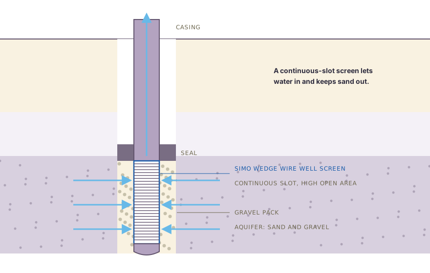
A tube well or borewell has blank casing through the upper strata and the tube well screen in the water-bearing zone. In alluvial aquifers a gravel pack fills the annulus between the screen and the borehole wall, and a sanitary seal at the top keeps surface water out. Water flows from the aquifer through the gravel pack and the slots into the well, and the pump lifts it from inside the casing. Drillers often call the screened section a borewell screen pipe.
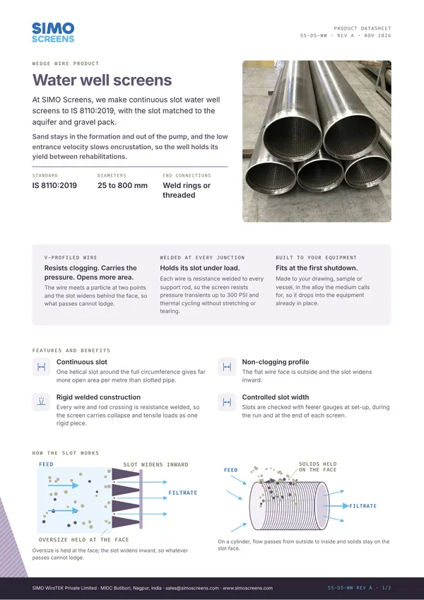
A failing well usually shows sand in the water, a falling yield or a deeper pumping level, and the screen is frequently the cause. Slotted mild steel and PVC pipe have uneven, wide slots that pass fine sand, while cut or drilled slots give a small open area, so water enters fast and drawdown rises. High entrance velocity and iron bacteria also build encrustation on the slots, and mild steel screens corrode through over time.
Swipe to see the full drawing.
Design considerations for an IS 8110 screen
Slot. The slot is set from a sieve analysis. For a gravel packed well, a slot that retains about 90 percent of the pack is common practice, and for a naturally developed well the slot is chosen against the aquifer grading. The pack itself is commonly graded with a D50 about 4 to 6 times the aquifer D50, and where the consultant has already selected the pack, its grading sets the slot.
Profile and open area. The V-profile slot is continuous around the screen and widens inward, so that a grain which passes the face does not lodge in the slot. Open area (%) = Slot x 100 / (Slot + Wire width), so a 0.5 mm slot on 15SB wire, 1.52 mm wide, gives about 25 percent.
Effective open area. Part of the slot area is blocked by gravel pack grains and formation in contact with the screen. In screen length estimates the effective open area is typically taken as about 50 percent of the calculated open area, which corresponds to a factor of safety of 2. Where the client's design uses a different factor of safety, including values below 2, the length is calculated to the client's requirement.
Collapse strength. Shallow wells in soft formations can use standard profiles such as 15SB or 18SB. Deep wells need more collapse strength, so the design moves to 28SB or 35SB wire and heavier rods, checked by FEA on custom designs.
Sizing for entrance velocity
A commonly used design limit for well screen entrance velocity is about 0.03 m/s. Screen length = Flow / (pi x Diameter x Open area x Effective fraction x Velocity).
For 50 m³/h (0.0139 m³/s), a 200 mm screen and 25 percent open area, with half the open area taken as effective, the screen length is about 5.9 m. A different factor of safety changes the effective fraction and the length in proportion. The well screen calculator runs the same method for other wells.
Construction and options
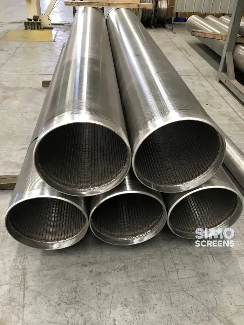
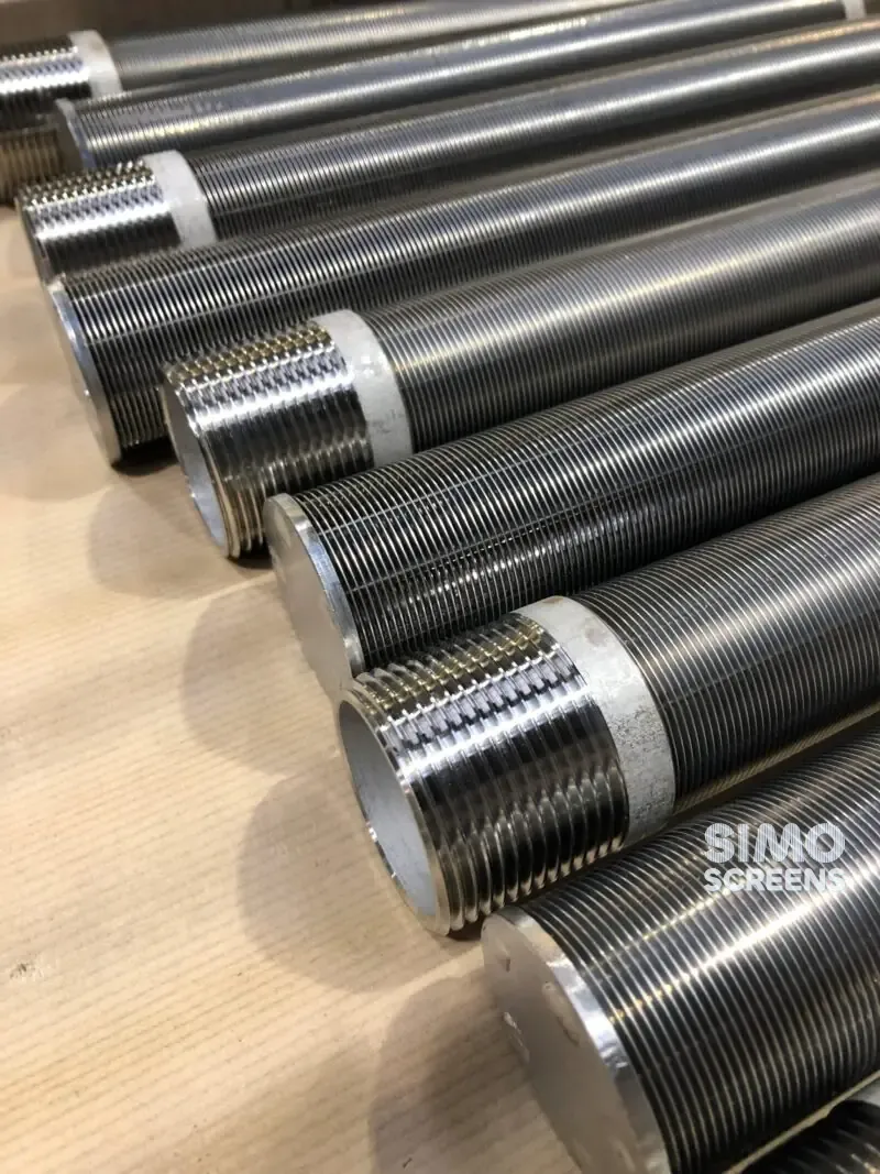
SIMO profile wire is formed in house and wrapped around longitudinal support rods, with resistance welding at every intersection, to form a rigid continuous slot cylinder. Slot width is checked with feeler gauges at set-up, during the run and at the end of each screen, and the final inspection report records the minimum, maximum and mean slot.
| Item | SIMO range or typical value |
|---|---|
| Standard | IS 8110:2019 |
| Slot opening | 25 microns (0.025 mm) to 25 mm, set from sieve analysis |
| Slot tolerance | Plus or minus 5% of nominal, stated on the drawing |
| Diameter | 25 to 800 mm |
| Length | Up to 6,000 mm per section |
| Profile wire | 15SB, 18SB, 28SB, 35SB, 42SB |
| Support rods | Q35, Q55, F123, round 120, round 140 |
| Flow direction | Radial external, outside to inside |
| End connections | Weld rings, threaded ends and bottom plugs, to standard |
Swipe sideways to see the whole table.
End rings and collars are fabricated to join the casing, and blank pipe sections are supplied where required. Each screen section is identified with job number, item and slot on a QR-coded tag, and laser marked where the client requires it.
Materials
SS 304 suits most fresh groundwater, and SS 316L is used for saline or aggressive water. Duplex 2205 or Super Duplex 2507 is selected for coastal aquifers with high chlorides. The Mill Test Certificate is supplied as standard, with heat numbers traceable to the finished screen.
Replacement and retrofit
A screen in an old well can rarely be replaced in place. Where space allows, a smaller wedge wire screen can be telescoped inside a failed one, with a new gravel pack. For new wells, the driller's log and sieve analysis determine the slot, the pack and the screen positions, so both should be retained and shared with the enquiry.
Our water well screens page gives the full range, and the water well screen design guide explains slot, length and entrance velocity in more detail.
What to send for a quotation
- Borehole diameter and total depth.
- Casing size, material and joint type.
- Driller's log with the depth and thickness of each aquifer.
- Sieve analysis of aquifer samples, and the gravel pack grading if chosen.
- Design yield, pumping level and the factor of safety you use.
- Water quality: chlorides, iron and pH.
- Screen lengths and positions, if already designed.
- End connection type at top and bottom.

 Upload a drawing