 +91 93730 08466
 Screen tubes and pipes
 Screen cylinders
 Flat panels and false bottoms
 Candle filter elements
 Water well screens
 Header and hub laterals
 Filter nozzles
 Resin traps
 Support grids
 Sieve bend (DSM) screens
 Centrifuge baskets
 Pressure screen baskets
 Screw press screens
 Rotary drum screens
 Passive intake screens
 Coanda intake screens
 Water and wastewater treatment
 Water wells and groundwater
 Sugar and distillery
 Brewing, malting and beverages
 Food processing
 Mining and minerals
 Oil, gas and petrochemicals
 Chemicals, fertilisers and pharma
 Power generation
 Pulp and paper
 Buildings and drainage
What is a resin trap
A resin trap for ion exchange service is an inline strainer fitted downstream of the vessel, and its function is to keep the resin inside the vessel. Ion exchange resin is costly and difficult to replace at short notice. When a lateral cracks or a nozzle breaks, resin can leave a vessel within minutes, after which it fouls the next vessel, blocks valves and damages pumps.
A resin trap is therefore a protective device. In normal service it passes water with a small pressure drop, and when a component fails upstream it catches the resin and signals the failure through a rising differential pressure.
How a wedge wire resin trap works
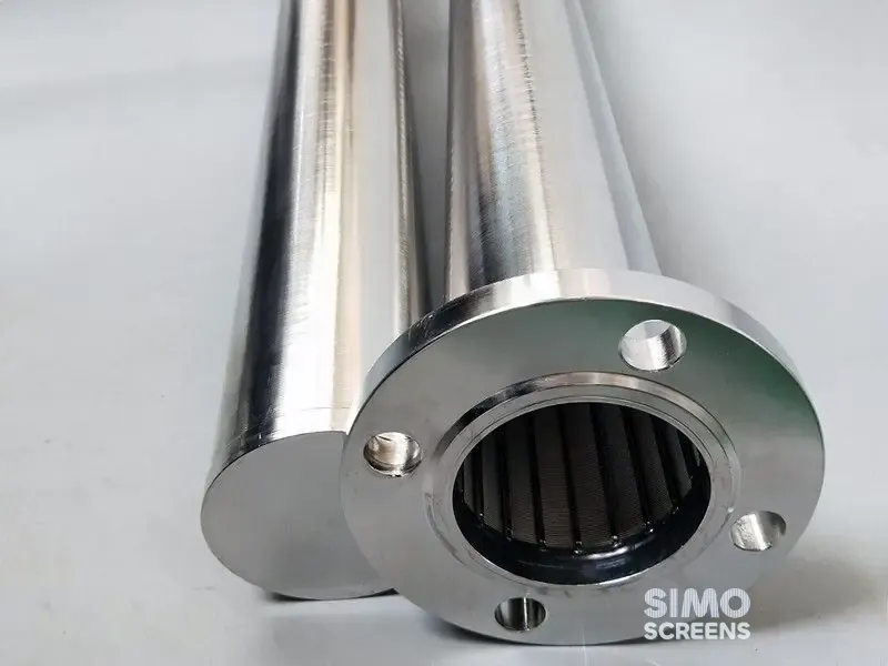
A wedge wire resin trap consists of a cylindrical screen element inside a flanged housing. Water passes through the slots to the outlet, while whole beads are retained on the screen.
The V-shaped slot is narrow on the inlet side and widens behind it, so a bead is either held at the face or, if it is a fragment small enough to enter, passes through. Beads do not wedge in the slot, which keeps the trap easy to clean and the slot at its original size.
The common flow arrangements are inside to outside, where caught resin stays within the element, and outside to inside. The choice depends on the housing design and on how resin is to be removed during cleaning.
Step 1: slot selection from the resin data
The resin data sheet gives the particle size range and the lower limit, often stated as a maximum percentage below a given size.
| Resin type | Typical size information | Slot approach |
|---|---|---|
| Standard grade gel or macroporous resin | About 0.3 to 1.2 mm (16 to 50 mesh) | Slot of about 0.2 to 0.25 mm |
| Uniform particle size resin | Narrow band around a stated mean | Slot below the stated lower limit |
| Fine mesh resin | Smaller beads | Slot from the data sheet lower limit |
| Inert resin layers in layered beds | Stated by the supplier | Checked separately |
Swipe sideways to see the whole table.
The trap is intended to catch whole beads rather than fines from resin breakdown, since a slot fine enough to retain every fragment would blind quickly and add unnecessary pressure drop.
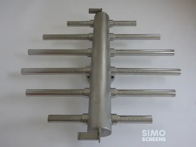
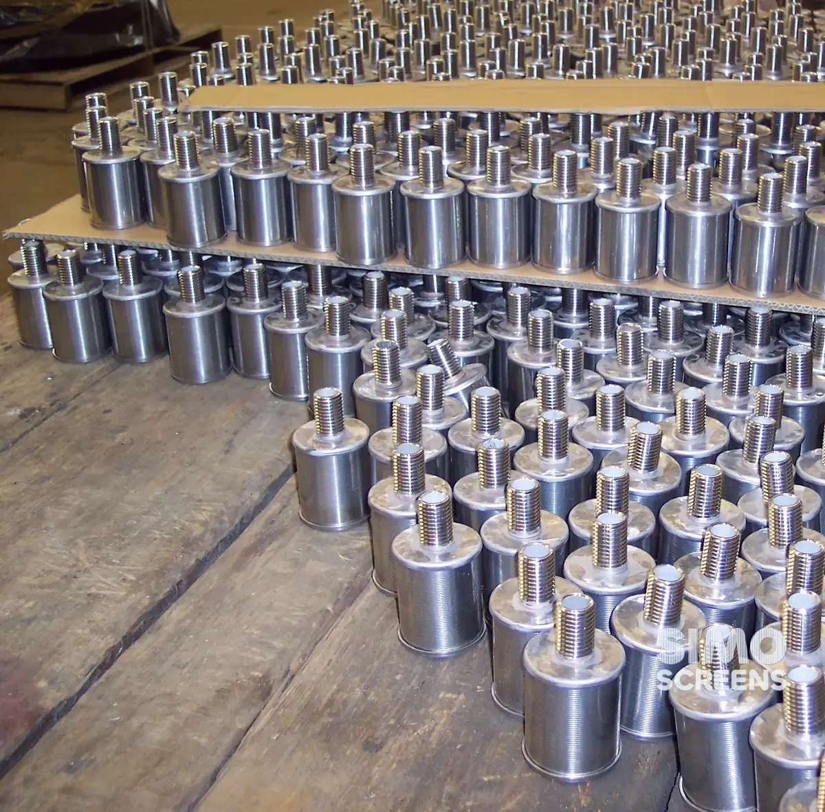
The trap slot follows the same logic as the internal laterals or nozzles of the vessel, so that resin reaching the trap indicates a failure of those internals. The header and lateral design guide covers the vessel internals.
Step 2: placement in the plant
Resin traps are fitted wherever escaped resin would cause damage:
- treated water outlet of each vessel, whether cation, anion, mixed bed or polisher, which is the primary location;
- condensate polisher outlets, where resin entering the boiler feed system is a serious risk, so traps are standard practice;
- backwash and rinse outlets, to catch resin lost during regeneration, particularly when backwash flow is set too high;
- upstream of pumps and meters on lines fed directly from vessels.
The trap is installed with the flow arrow in the correct direction, with isolation valves on both sides, a drain, a vent at the high point and pressure gauges or a differential pressure gauge. Space is left to withdraw the element.
Step 3: resin trap sizing for pressure drop
A resin trap must not become the main pressure loss in the line, so its clean pressure drop is kept small compared with the rest of the system. Two parameters guide resin trap sizing:
- open area of the element, commonly specified as a multiple of the pipe bore area, often 3 times or more;
- velocity through the slots, since a lower velocity reduces both the pressure loss and the force pressing caught beads into the screen.
Open area follows from the slot and the wire width:
Open area (%) = Slot x 100 / (Slot + Wire width)
A fine slot gives a low open area with standard wire, and a narrower wire raises the open area for the same slot at some cost in strength.
The element must also withstand the full differential pressure if it becomes completely blocked. Welded wedge wire is rigid, but the profile wire and support rods are selected for the operating conditions, and SIMO Screens uses CFD to predict pressure drop and FEA to check the structure of custom designs.
Worked example: DN 100 line on a mixed bed outlet
Design basis: treated water at 60 m³/h leaves a mixed bed through a DN 100 line, with standard grade resin of about 0.3 to 1.2 mm.
Pipe:
- Bore area (taking 100 mm) = π x 0.1² / 4 = 0.00785 m²
- Flow = 60 / 3,600 = 0.0167 m³/s
- Pipe velocity = 0.0167 / 0.00785 = 2.1 m/s
Slot: 0.25 mm, below the 0.3 mm lower bead size.
Open area for two wire choices:
| Wire | Width | Open area |
|---|---|---|
| 15SB | 1.52 mm | 0.25 x 100 / 1.77 = 14.1% |
| 12SB | 1.0 mm | 0.25 x 100 / 1.25 = 20.0% |
Swipe sideways to see the whole table.
Element size at 3 times the bore area:
- Required open area = 3 x 0.00785 = 0.0236 m²
- With 15SB: screen surface = 0.0236 / 0.141 = 0.167 m²
- At 150 mm element diameter, length = 0.167 / (π x 0.15) = 0.35 m
- With 12SB: screen surface = 0.118 m², length 0.25 m at 150 mm diameter
Slot velocity: 0.0167 / 0.0236 = 0.71 m/s in both cases.
The 12SB element is shorter, while the 15SB element is stiffer and has a greater wear margin. The final choice rests on the blocked-condition differential pressure the element must carry. The open area calculator tests other slot and wire combinations.
Step 4: cleaning and inspection
A resin trap is cleaned when its differential pressure rises, and at planned shutdowns.
- Isolate the trap and drain the housing.
- Open the cover and withdraw the element.
- Collect and examine the captured material before washing.
- Flush the element from the clean side with low-pressure water.
- Inspect the slots and welds, then refit with a new gasket.
The captured material indicates the condition of the vessel. Whole beads usually mean a failed lateral, nozzle or screen, while fragments point to resin breakdown from osmotic shock, oxidation or mechanical wear. Clean whole beads can often be returned to the vessel with the resin supplier's agreement. The screen face is never scraped across the slots with a wire brush, as this can burr the wire edges and alter the slot.
Housing and connections
The housing carries the line pressure, so it is designed to the plant's pressure and code requirements, and the enquiry should state the design pressure, test pressure and design temperature. SIMO Screens supplies stainless steel housings, with carbon steel or lined housings available on request.
End connections match the pipework, usually flanged to the plant's flange standard, and a quick-opening or bolted cover simplifies element removal. Rubber-lined pipework may call for a lined housing, or a stainless housing with suitable isolation at the flanges. A sight glass lets operators see captured resin without opening the trap, and on large lines a twin arrangement with a changeover valve keeps the plant running while one element is cleaned.
Material selection
SS 304 and SS 316L suit most treated water and condensate service. Standard stainless steels are attacked by hydrochloric acid, so traps on lines that may carry acid regenerant need a separate material review, for which Hastelloy C-276 is among the options.
SIMO Screens resin traps
SIMO Screens manufactures wedge wire resin traps and the header and hub lateral assemblies they protect, for DM plants, condensate polishers and process ion exchange. Send the line size, flow, pressure, resin data sheet and the vessel served, and our engineers will size the element and housing.