 +91 93730 08466
 Screen tubes and pipes
 Screen cylinders
 Flat panels and false bottoms
 Candle filter elements
 Water well screens
 Header and hub laterals
 Filter nozzles
 Resin traps
 Support grids
 Sieve bend (DSM) screens
 Centrifuge baskets
 Pressure screen baskets
 Screw press screens
 Rotary drum screens
 Passive intake screens
 Coanda intake screens
 Water and wastewater treatment
 Water wells and groundwater
 Sugar and distillery
 Brewing, malting and beverages
 Food processing
 Mining and minerals
 Oil, gas and petrochemicals
 Chemicals, fertilisers and pharma
 Power generation
 Pulp and paper
 Buildings and drainage

Condensate polisher internals overview
A condensate polishing unit (CPU) cleans turbine condensate before it returns to the boiler, removing iron oxide crud and the dissolved salts that enter through condenser tube leaks. Most thermal plants use deep bed mixed bed polishers, which in general practice run at service velocities of about 100 to 125 m/h and send resin to external vessels for regeneration.
The CPU internals sit inside each vessel: an inlet distributor spreads the flow, an underdrain collects it through the resin bed, and a resin trap protects the outlet line. A fault in any of them quickly becomes a boiler chemistry problem. Damaged laterals or wide slots let resin into the feedwater, crud blinding crowds flow through clear zones, and incomplete resin transfer leaves a heel that mixes regenerated and exhausted resin.
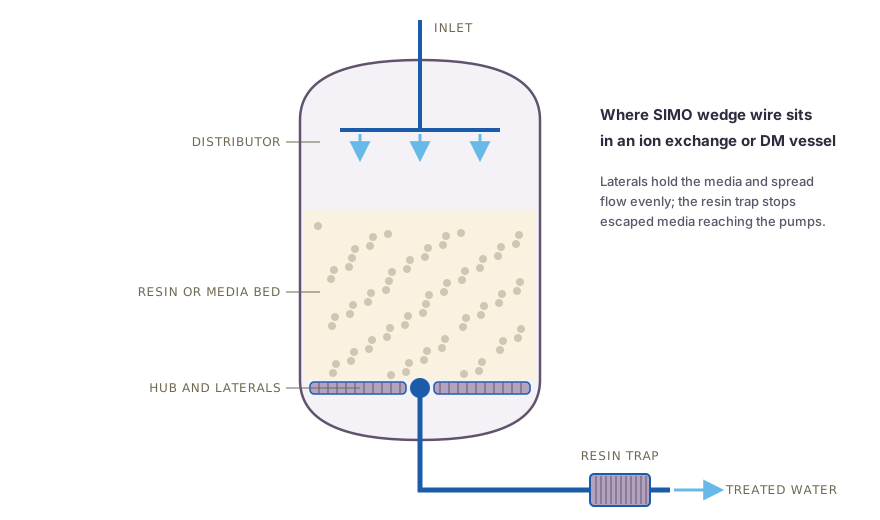
Swipe to see the full drawing.
Design considerations for a condensate polisher lateral
Slot. The slot sits below the smallest resin bead with a margin. Polishers commonly use uniform particle size resins, for which a slot of about 0.2 mm is typical, and the slot is checked against the resin data sheet before drawings are issued.
Profile and open area. Fine slots call for light profiles such as 12SB on Q23 or Q35 rods, with heavier rods for long laterals. Open area (%) = Slot x 100 / (Slot + Wire width), so a 0.2 mm slot on 12SB wire, 1 mm wide, gives about 17 percent open area. Options can be compared in the open area calculator.
Distribution. Laterals are laid out from the vessel diameter and service flow so that each collects a similar share of the flow, which avoids early breakthrough in one zone. CFD is used to check distribution on custom layouts.
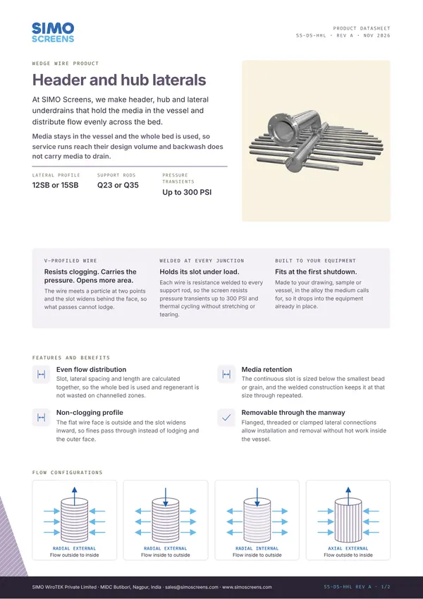
Load and pressure. High service flow, pressure surges and resin transfer forces fatigue plastic and thin-walled laterals at the root. The welded wedge wire construction resists thermal cycling and pressure transients up to 300 PSI.
Resin transfer. The underdrain and transfer outlet are arranged for full resin transfer to external regeneration, leaving as small a heel as possible.
Construction and options
SIMO profile wire is formed in house and wound over support rods, with resistance welding at every wire and rod intersection. Slot width is checked with feeler gauges at set-up, during the run and at the end of each screen, and the final inspection report records the minimum, maximum and mean slot.
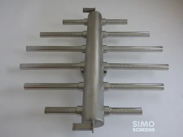
Underdrain laterals and hub. Laterals are wedge wire screen tubes on a header or hub, with segments sized to pass the manway.
Inlet distributors. Wedge wire laterals or baskets spread incoming condensate across the bed without disturbing it.
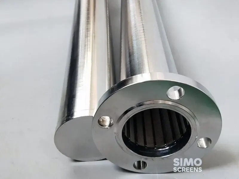
Resin traps. The outlet resin trap is a wedge wire element in a flanged housing, with differential pressure tappings as a standard feature. See our resin traps for housing options.
| Item | SIMO range or typical value |
|---|---|
| Items | Inlet distributors, hub or header laterals, resin traps |
| Slot opening | 25 microns (0.025 mm) to 25 mm; polisher laterals typically about 0.2 mm |
| Slot tolerance | Plus or minus 5% of nominal, stated on the drawing |
| Profile wire | 12SB, 15SB, 18SB |
| Support rods | Q23, Q35, Q55 |
| Lateral length | Up to 6,000 mm |
| Pressure | Welded construction resists pressure transients up to 300 PSI |
| Resin trap | Differential pressure tappings as standard |
Swipe sideways to see the whole table.
Materials
SS 316L is the usual material for condensate service. Duplex 2205 or Super Duplex 2507 is selected for seawater cooled plants, where condenser tube leaks raise chlorides. The Mill Test Certificate is supplied as standard, and a dimensional inspection report, QAP, PMI, and pickling and passivation through approved agencies are available on request.
Replacement and retrofit
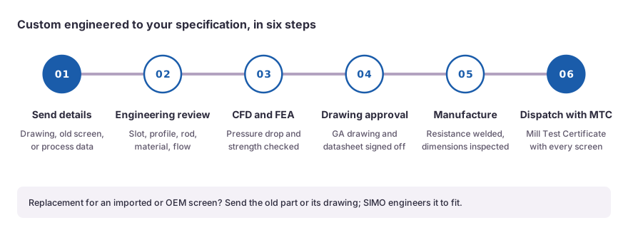
Polisher internals are usually changed during a unit outage. Existing internals, including imported and OEM designs, are replaced from a sample or a drawing, and the vessel and internals drawings should be shared early so that drawings are approved before the outage starts. The resin trap element should be inspected at every opening, and its differential pressure trend reviewed between openings.
Where the old underdrain is a nozzle plate, a header and lateral system removes the plate welds and the risk of a cracked nozzle, subject to a check of the vessel nozzles and supports. Our header and hub lateral assemblies and the header and lateral underdrain design guide give more detail, and DM plant laterals covers softeners and DM vessels.
What to send for a quotation
- Polisher type and number of vessels in service and standby.
- Vessel diameter, design pressure and design temperature.
- Service flow per vessel.
- Resin type and data sheet, including the smallest bead size.
- Underdrain type now in use and the resin transfer arrangement.
- Outlet pipe size and flange rating, for the resin trap.
- Condenser cooling water type, fresh or seawater.
- Vessel and internals drawings.

 Upload a drawing