 +91 93730 08466
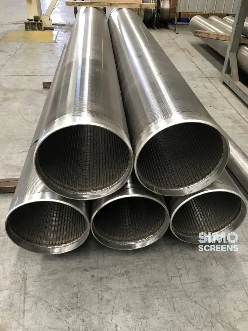
 Screen tubes and pipes
 Screen cylinders
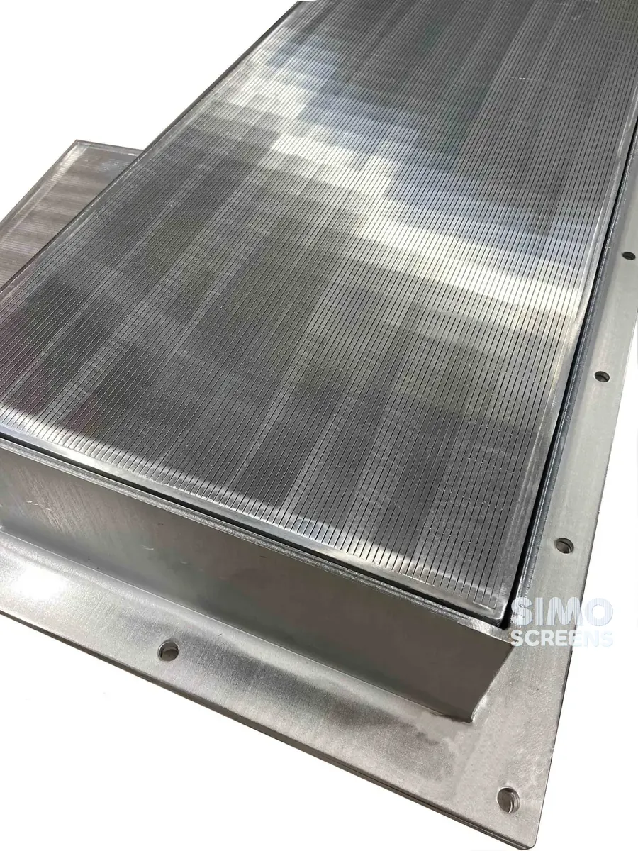
 Flat panels and false bottoms
 Candle filter elements
 Water well screens
 Header and hub laterals
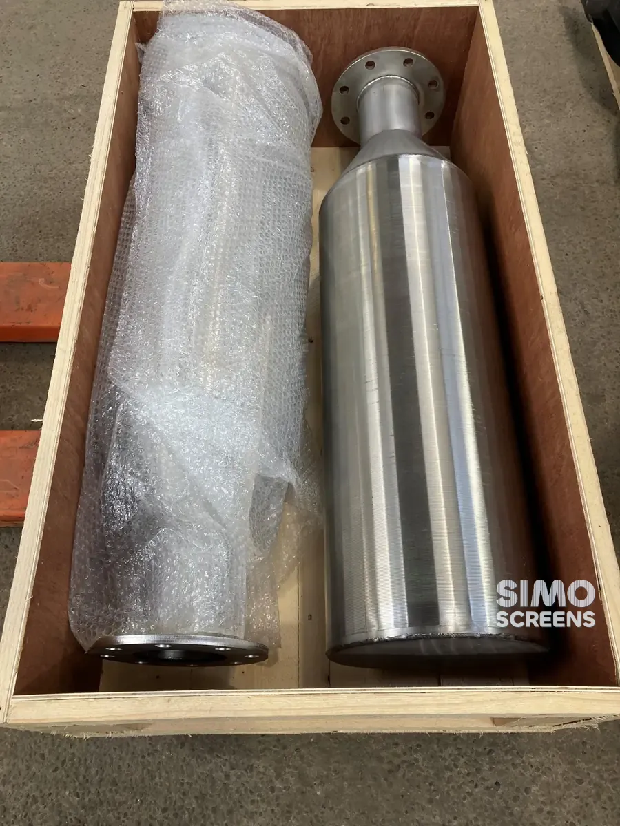
 Filter nozzles
 Resin traps
 Support grids
 Sieve bend (DSM) screens
 Centrifuge baskets
 Pressure screen baskets
 Screw press screens
 Rotary drum screens
 Passive intake screens
 Coanda intake screens
 Water and wastewater treatment
 Water wells and groundwater
 Sugar and distillery
 Brewing, malting and beverages
 Food processing
 Mining and minerals
 Oil, gas and petrochemicals
 Chemicals, fertilisers and pharma
 Power generation
 Pulp and paper
 Buildings and drainage
The two design checks for a wedge wire screen
Every wedge wire screen is sized against two sets of requirements. Hydraulically, it must pass the design flow without excessive velocity or pressure drop; structurally, it must hold its shape under pressure, weight and rotation.
A hydraulic error leads to lost head, sand pumping or fish entrainment, while a structural error leads to deflection, collapse or separation of the screen. The worked examples below use typical values, labelled as such, to show the method; they are not ratings for any product, and SIMO Screens designs each screen from the customer's process data.
Open area calculation from slot and wire width
Open area is the proportion of the screen face that is slot. For wedge wire:
Open area (%) = Slot x 100 / (Slot + Wire width)
Worked example 1: open area
| Slot (mm) | Profile wire | Wire width (mm) | Open area |
|---|---|---|---|
| 0.5 | 15SB | 1.52 | 0.5 x 100 / 2.02 = 24.8% |
| 1.0 | 15SB | 1.52 | 1.0 x 100 / 2.52 = 39.7% |
| 1.0 | 35SB | 3.0 | 1.0 x 100 / 4.0 = 25.0% |
| 3.0 | 35SB | 3.0 | 3.0 x 100 / 6.0 = 50.0% |
Swipe sideways to see the whole table.
A wider wire carries more load but lowers the open area at the same slot. The slot and open area guide covers the trade-off, and the open area calculator performs the arithmetic.
Through-slot velocity and required screen area
Velocity through the slots governs wear, entrainment and fish safety. The basic relation is:
Through-slot velocity = Flow / (Screen area x Open area fraction)
which rearranges to: Required screen area = Flow / (Design velocity x Open area fraction)
Worked example 2: intake screen
- Flow: 0.5 m³/s.
- Design through-slot velocity: 0.15 m/s, a value typically used for fish-protection intakes.
- Slot 3 mm on 3 mm wire, giving an open area of 0.50.
Required area = 0.5 / (0.15 x 0.50) = 6.7 m².
Debris blocks part of any intake screen. Where the design basis allows for 25 percent blockage, the area becomes 6.7 / 0.75 = 8.9 m². A cylindrical screen provides π x D x L of surface, so two screens of 0.8 m diameter need about 1.8 m of screen length each. The intake screen calculator applies the same method to passive intake screens.
Worked example 3: water well screen
- Yield: 20 m³/h, or 0.0056 m³/s.
- Entrance velocity limit: about 0.03 m/s, a commonly used design limit.
- Slot 1 mm on 15SB wire, giving an open area of 39.7 percent. Effective open area is commonly taken as about half of this, allowing for blockage by formation or pack grains, so about 19.8 percent.
Required area = 0.0056 / (0.03 x 0.198) = 0.94 m². For a 150 mm diameter screen, π x 0.15 = 0.47 m² per metre, so at least 2.0 m of screen is needed, although the aquifer thickness usually sets a longer length. The well screen calculator runs this check.
Screen pressure drop: a clean-screen estimate
A clean wedge wire slot behaves much like a short orifice, for which a simple estimate is:
Pressure drop = (ρ / 2) x (Through-slot velocity / Cd)²
where ρ is the fluid density and Cd the discharge coefficient, for which values of 0.6 to 0.8 are a reasonable assumption for a sharp-edged slot.
Worked example 4: clean pressure drop (estimate)
| Case | Through-slot velocity | Cd assumed | Estimated clean pressure drop |
|---|---|---|---|
| Intake screen, water | 0.15 m/s | 0.6 | 500 x (0.15 / 0.6)² = 31 Pa, about 3 mm of water |
| Strainer element, water | 1.0 m/s | 0.6 | 500 x (1.0 / 0.6)² = 1,390 Pa, about 0.014 bar |
Swipe sideways to see the whole table.
This estimate applies to a clean screen only. It excludes housing, approach and exit losses and any media bed. In service, solids build up on the face and the pressure drop rises, so the design is made for the fouled condition with a cleaning or alarm point, and CFD or test data are used where the margin is tight.
Collapse resistance of a well screen
The principle
A well screen under external pressure behaves as a stack of rings: the wrap wire carries the load in hoop compression, and the support rods hold the rings in line. For an ideal elastic ring, the critical external pressure is:
Critical pressure ≈ 3 x E x I / R³
where E is the elastic modulus, I the second moment of area of the wrap wire per unit length of screen and R the mean radius. Collapse resistance therefore rises with the cube of wire height and falls with the cube of radius, so doubling the diameter reduces resistance about eight times.
Real screens fall short of the ideal, because ovality, weld quality, slot width and end connections all reduce the collapse resistance. Collapse ratings are therefore based on tests or validated calculations, and the basis of any figure quoted should be stated.
The load cases
| Load case | Cause | Estimation |
|---|---|---|
| Hydrostatic | Water level outside higher than inside, worst when the screen blinds and the well is pumped down | ρ x g x head difference |
| Grouting | Cement grout placed in the annulus above or around the screen while the screen holds water | (Grout density minus water density) x g x grout height |
| Development | Pressure swings from surging, swabbing, airlifting and jetting | Difficult to calculate; intensity is limited and margin kept |
| Gravel pack and formation | Pack placement, bridging and heaving sand | Judgement and site practice |
Swipe sideways to see the whole table.
Worked example 5: required collapse rating
- Hydrostatic case: a head difference of 40 m of water gives 1,000 x 9.81 x 40 = 392 kPa, or 3.9 bar.
- Grouting case: with grout specific gravity assumed at 1.8 and a grout height of 30 m, (1,800 minus 1,000) x 9.81 x 30 = 235 kPa, or 2.4 bar.
- Governing case: 3.9 bar. With a safety factor of 2, assumed for this example, the screen needs a collapse rating of at least 7.8 bar.
The safety factor comes from the project specification or the designer, and the profile wire and support rods are selected to meet the rating, as described in the profile wire selection guide.
IS 8110:2019
IS 8110:2019 is the Indian Standard for well screens and slotted pipes, and Indian tenders for tube wells and borewells often call for it. The tender requirements should be checked, and the manufacturer asked to state how any collapse figure was established. SIMO Screens makes water well screens to IS 8110:2019.
Panel deflection of a flat screen or support grid
In a flat panel, false bottom or support grid, the support rods span between beams, and each rod can be treated as a simply supported beam under a uniform load:
Maximum deflection = 5 x w x L⁴ / (384 x E x I)
Maximum bending moment = w x L² / 8
Here w is the load per unit length on one rod, equal to the pressure multiplied by the rod pitch, L is the span and I the rod's second moment of area, b x h³ / 12. A typical design criterion limits deflection to span/200, and a common approach limits bending stress to about two-thirds of yield unless the governing code states otherwise.
Worked example 6: panel deflection in mm
- Load: 10 kPa (0.01 N/mm²), from bed weight plus pressure difference.
- Rod pitch: 50 mm, so w = 0.01 x 50 = 0.5 N/mm.
- Span: 600 mm, giving a limit of 600 / 200 = 3.0 mm.
- Material: SS 316L, E = 193,000 N/mm², minimum 0.2 percent proof stress 170 N/mm².
| Support rod | I (mm⁴) | Deflection | Bending stress | Result |
|---|---|---|---|---|
| F203 (3 x 20 mm) | 3 x 20³ / 12 = 2,000 | 2.19 mm | 22,500 / 200 = 113 N/mm² | Deflection passes; stress at two-thirds of yield, with no margin |
| F253 (3 x 25 mm) | 3 x 25³ / 12 = 3,906 | 1.12 mm | 22,500 / 313 = 72 N/mm² | Passes both checks |
Swipe sideways to see the whole table.
Span has the greatest effect: doubling the span to 1,200 mm raises deflection sixteen times. For this reason large flat panels and false bottoms rest on intermediate beams. SIMO Screens makes single flat panels up to 2,400 mm wide and 4,000 mm long, and larger decks are engineered as joined panels.
Axial and tensile load on long screen strings
A well screen string is lowered from the top, so the top joint carries the weight of everything suspended below it.
Worked example 7: tensile load
- Suspended below the joint: 60 m of screen and blank pipe at an assumed 12 kg/m.
- Weight in air: 60 x 12 x 9.81 = 7.1 kN, reduced by about one-eighth by buoyancy below the water level for steel.
- Rod capacity: 24 round 140 rods of 3.6 mm diameter give 24 x 10.2 = 244 mm², which at 170 N/mm², a conservative illustration, carry about 41 kN before yield.
The rods have ample margin in this case. In practice the end ring weld or threaded connection often governs, so the joint is checked as well as the rods, with an allowance for pull-back if the string sticks. When the string lands on the bottom, the lowest joints carry compression instead.
Centrifugal load on a basket
In a centrifuge, the screen carries the cake at many times its weight. The multiplier is:
G = ω² x r / g, where ω = 2 x π x rpm / 60.
Worked example 8: g-force
A 1,000 mm basket at 1,800 rpm has ω = 188.5 rad/s, so G = 188.5² x 0.5 / 9.81 = about 1,800 g. Each kilogram of cake therefore presses on the screen with a force equal to the weight of about 1.8 tonnes, which is why centrifuge baskets are designed with heavy support rods and checked by FEA.
CFD and FEA in screen design
Hand calculations set the first design, and some applications need more detailed analysis. SIMO Screens uses CFD for pressure drop prediction and FEA for structural validation of custom designs.
| Method | Applications | Results |
|---|---|---|
| CFD | Flow distribution in header and lateral systems, intakes and outlet collectors | Flow uniformity, local velocity peaks, pressure drop |
| FEA | Support grids, baskets and high-g centrifuge baskets | Stress at welds and openings, deflection, fatigue hot spots |
Swipe sideways to see the whole table.
The design engineering page describes how process data become an approved drawing. Send the application and operating conditions with your enquiry, and our engineers will carry out the calculations for your screen.