 +91 93730 08466
 Screen tubes and pipes
 Screen cylinders
 Flat panels and false bottoms
 Candle filter elements
 Water well screens
 Header and hub laterals
 Filter nozzles
 Resin traps
 Support grids
 Sieve bend (DSM) screens
 Centrifuge baskets
 Pressure screen baskets
 Screw press screens
 Rotary drum screens
 Passive intake screens
 Coanda intake screens
 Water and wastewater treatment
 Water wells and groundwater
 Sugar and distillery
 Brewing, malting and beverages
 Food processing
 Mining and minerals
 Oil, gas and petrochemicals
 Chemicals, fertilisers and pharma
 Power generation
 Pulp and paper
 Buildings and drainage
Water well screen design and well life
The well screen governs how long a tube well delivers its design yield. A slot that is too wide pumps sand, wears the pump and leaves a cavity behind the screen, while a slot that is too fine, or a screen with low open area, raises drawdown and encrusts quickly.
Design starts from the aquifer data: a sieve analysis, a drilling log and a target yield. The screen is then sized in sequence for slot, length and diameter, followed by an entrance velocity check.
A welded wedge wire well screen is often called a Johnson screen, a trade name of Johnson Screens (Aqseptence Group) that is used generically; SIMO Screens is not affiliated with that company. Its slot is continuous around the screen, which gives a high open area, and the V-profile wire forms a slot that widens inward, so grains that enter pass through rather than wedge.
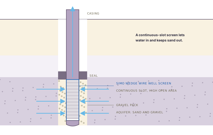
Swipe to see the full drawing.
Step 1: sieve analysis of the formation
Formation samples are collected at regular depth intervals and at every change in formation. Each sample is washed, dried and sieved, and the cumulative percent retained is plotted against grain size. The following sizes are read from the curve.
| Term | Meaning |
|---|---|
| 70 percent retained size | Size at which 70 percent of the sample is coarser, used to size a gravel pack |
| 40 percent and 90 percent retained sizes | Used for the uniformity coefficient |
| Uniformity coefficient (Cu) | 40 percent retained size divided by 90 percent retained size; below about 3 is uniform and above about 6 is well graded |
| Effective size | The 90 percent retained size, an indication of how fine the sand is |
Swipe sideways to see the whole table.
The design is based on the finest layer to be screened. Where layers differ widely, different slots can be used in different sections of one screen string.
Step 2: natural pack or gravel pack
Naturally developed wells
In a coarse or well-graded formation, the well can be developed so that the formation itself forms a stable pack around the screen. Surging or airlifting draws the fines out through the slot, and the coarser grains left behind bridge against it.
Common practice is a slot that retains roughly 40 to 60 percent of the formation. The finer slot, at the higher retention, is selected when the water is corrosive, the sample is doubtful or a fine layer lies above the screened zone.
Gravel-packed wells
A gravel pack is used when the formation is fine and uniform, so that a natural pack would need an impractically fine slot, and where thin fine and coarse layers alternate. The widely used procedure is as follows.
- Multiply the 70 percent retained size of the finest formation layer by 4 to 6, using 4 for fine, uniform sand and 6 for coarser, graded sand. The result is the 70 percent retained size of the pack.
- Select a pack with a uniformity coefficient of 2.5 or less, made of clean, rounded quartz grains.
- Select a screen slot that retains 90 percent or more of the pack.
- Keep the pack thick enough to place reliably, commonly about 75 to 200 mm.
Slot numbers follow thousandths of an inch: slot 10 is about 0.25 mm, slot 20 about 0.5 mm and slot 40 about 1.0 mm.
Step 3: well screen length
Well screen length is set mainly by the aquifer and then checked against entrance velocity.
- Unconfined aquifer: the lower one-third to one-half of a homogeneous aquifer is screened, which leaves room for drawdown above the screen.
- Confined aquifer: most of the water-bearing thickness is screened, typically 70 to 90 percent, provided the pumping level stays above the top of the aquifer.
- Layered aquifers: the most permeable layers are screened, with blank casing against clay bands.
The pumping water level should stay above the top of the screen, because alternate exposure to air and water accelerates encrustation and corrosion.
Step 4: screen diameter
The pump sets the minimum casing diameter, and the screen diameter follows the casing, the yield and the entrance velocity check. The yield gain from a larger diameter is modest, so length and open area usually have the greater effect. A larger diameter remains useful where it meets the entrance velocity limit without a finer slot or a longer screen.
The profile wire and support rods must also suit the depth and the collapse load. The profile wire selection guide describes the options.
Step 5: open area and entrance velocity
Open area is calculated from the slot and the wire width:
Open area (%) = Slot x 100 / (Slot + Wire width)
Entrance velocity is the pumped flow divided by the effective open area. A commonly used design limit is about 0.03 m/s (3 cm/s), below which friction loss through the slot stays low and the risk of sand movement and encrustation falls.
Common practice takes the effective open area as about 50 percent of the calculated open area, allowing for blockage by pack or formation grains, or applies the client's own design factor. The check is then:
V = Q / (π x D x L x OA x 0.5)
where Q is the flow in m³/s, D the screen outside diameter in m, L the screen length in m and OA the open area as a fraction.
Worked example: gravel-packed tube well
Design basis: a tube well in a confined sand aquifer 20 m thick, with a target yield of 20 L/s (0.020 m³/s, or 72 m³/h) and a screen outside diameter of 200 mm.
Pack and slot:
- The finest layer is fine, uniform sand with a 70 percent retained size of 0.30 mm.
- Pack 70 percent retained size = 0.30 x 4 = 1.2 mm.
- A graded pack with Cu below 2.5 is selected, with a 90 percent retained size of 1.0 mm.
- Slot = 1.0 mm (about slot 40), retaining 90 percent of the pack.
Open area: with a 28SB profile wire 2.2 mm wide:
OA = 1.0 x 100 / (1.0 + 2.2) = 31.3 percent
Length: about 75 percent of the confined thickness is screened, so L = 15 m.
Entrance velocity:
- Gross screen area = π x 0.2 x 15 = 9.42 m²
- Calculated open area = 9.42 x 0.313 = 2.95 m²
- Effective open area at 50 percent = 1.47 m²
- V = 0.020 / 1.47 = 0.0136 m/s, or 1.4 cm/s
This is well below 3 cm/s. The minimum length that meets 0.03 m/s would be:
L min = 0.020 / (π x 0.2 x 0.313 x 0.5 x 0.03) = 6.8 m
In this case the aquifer, rather than the velocity, sets the length. A 6.8 m screen would pass the velocity check but reduce specific capacity. The well screen calculator runs the same check for your own figures.
IS 8110:2019 and documentation
IS 8110:2019 is the Indian Standard specification for well screens and slotted pipes, and government and institutional tenders for tube wells and borewells often call for it. SIMO Screens makes water well screens to IS 8110:2019.
The Mill Test Certificate is supplied with every order, and every screen is dimensionally inspected before dispatch. The drawing should state slot, open area, diameter, length and end connections, and the dimensional inspection report is available on request.
Material, joints and installation
- Material: SS 304 suits most fresh groundwater, while SS 316L or a duplex grade is used where chloride is high or the water is aggressive.
- End connections: weld rings, threaded ends and bottom plugs are made to standard and matched to the casing, with an end cap or bail plug closing the bottom of the string.
- Centralisers: these keep the screen central so that the gravel pack is even all round.
- Development: surging or airlift development needs adequate time, and a continuous slot lets development energy reach the formation evenly.
- Recharge wells: the same slot and velocity logic applies where water flows outward into the aquifer.
Well screen proposals from SIMO Screens
SIMO Screens supplies water well screens to IS 8110:2019 for tube well and borewell projects, with slot and open area selected as described in the slot size and open area guide. Send the sieve analysis, drilling log and target yield, and our engineers will propose a slot, length and diameter. Our engineers will connect with you within a working day.