 +91 93730 08466
 Screen tubes and pipes
 Screen cylinders
 Flat panels and false bottoms
 Candle filter elements
 Water well screens
 Header and hub laterals
 Filter nozzles
 Resin traps
 Support grids
 Sieve bend (DSM) screens
 Centrifuge baskets
 Pressure screen baskets
 Screw press screens
 Rotary drum screens
 Passive intake screens
 Coanda intake screens
 Water and wastewater treatment
 Water wells and groundwater
 Sugar and distillery
 Brewing, malting and beverages
 Food processing
 Mining and minerals
 Oil, gas and petrochemicals
 Chemicals, fertilisers and pharma
 Power generation
 Pulp and paper
 Buildings and drainage
Intake screen design objectives
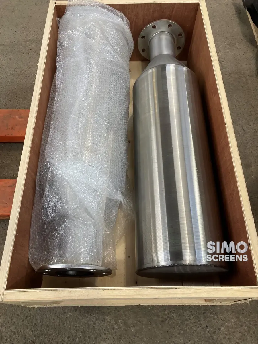
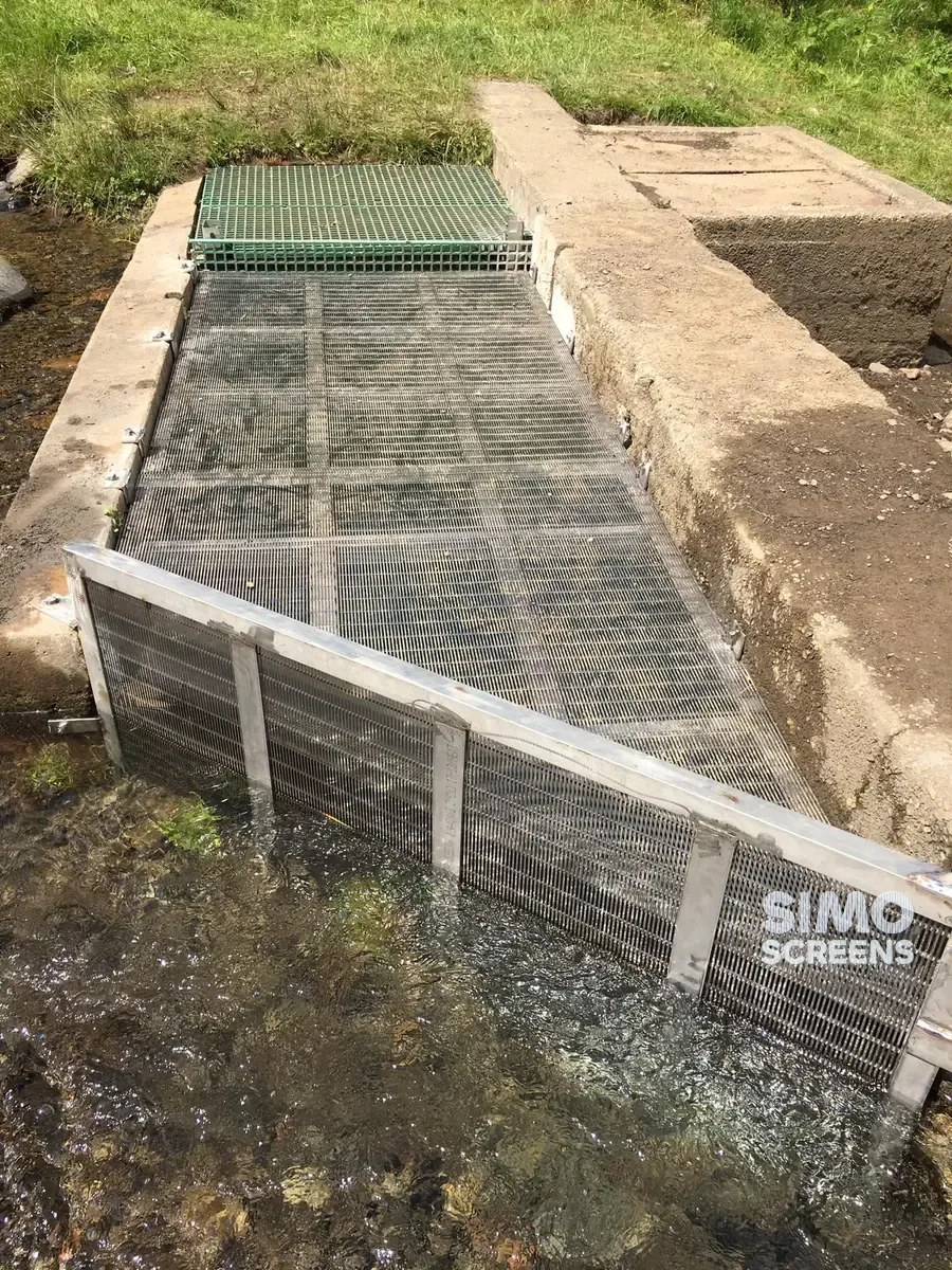
A raw water intake must draw a steady flow without drawing in fish, leaves, weed or sand. Travelling band screens achieve this with moving parts, wash pumps and a screen house, whereas a passive cylindrical wedge wire intake screen has no moving parts in the water.
The design rests on the velocity of water through the slots. A low through-slot velocity allows fish to swim clear, keeps debris from being pinned to the screen and lets the current sweep the face clean. An excessive velocity leads to blinding, loss of flow and pump cavitation.
Design basis: through-slot velocity
Through-slot velocity is the flow divided by the total open area of the slots, which is distinct from both the pipe velocity and the river velocity. Fish-protection intake screens are typically designed for a through-slot velocity of 0.15 m/s (0.5 ft/s) or less, checked at minimum water level with a clean screen.
Approach velocity, measured just outside the screen, is lower again. For a cylinder it is roughly the through-slot velocity multiplied by the open area fraction.
The intake screen sizing method
1. Flow to open area
Required open area (m²) = Q (m³/s) / V slot (m/s)
The peak design flow is used, including any future expansion the screen is expected to carry.
2. Open area to screen surface
Open area for wedge wire follows from the slot and the wire width:
Open area (%) = Slot x 100 / (Slot + Wire width)
Screen surface area (m²) = Required open area / Open area fraction
Only the cylindrical screen surface is counted, because end plates, the outlet and any blank bands carry no flow.
3. Surface area to diameter and length
Screen length (m) = Surface area / (π x D)
For a tee screen, this length is divided between the two drums. Diameter is selected to suit the outlet pipe, the available water depth and handling on site, and larger flows are often split across two or more screens so that one can be lifted for inspection while the others remain in service.
Slot selection
The slot sets what the screen excludes. It is selected from the smallest fish, fry or debris that must be kept out and from what the downstream treatment plant can accept.
Where a fisheries or environmental condition applies, its opening limit governs. As an example, US federal fisheries criteria limit profile bar screen openings to 1.75 mm for juvenile salmonids. In India, the conditions in the environmental clearance or the irrigation department's requirements should be checked.
A finer slot lowers the open area for the same wire, which makes the screen larger for the same velocity. The slot and open area guide sets out this trade-off.
Tee screen or single screen
| Feature | Tee screen | Single screen |
|---|---|---|
| Layout | Two drums either side of a central outlet | One drum on the end of the pipe |
| Flow pattern | Draws from both ends, evenly balanced | Draws from one end |
| Typical use | Larger flows, river and lake intakes, cooling water | Smaller flows, pump suctions, narrow channels |
| Mounting | On a riser or horizontal header | On the pipe end or a pump suction |
| Air burst provision | Header inside both drums, where fitted | Pipe inside the drum, where fitted |
Swipe sideways to see the whole table.
Both types usually include an internal flow modifier, an inner pipe with sized openings that evens out the slot velocity along the drum. Without it, the slots nearest the outlet carry more flow than those at the far end.
Siting and orientation
- Alignment with the current. The screen axis is set parallel to the river flow, so that the current sweeps along the screen face and carries debris away.
- Submergence. Generous water depth is kept above the screen at minimum level, with clearance above the bed; many designers allow at least about half a screen diameter for each.
- Sediment. The screen is kept out of eddies and slack water where silt and bed load settle.
- Access. Provision is made for divers, a crane or a rail system to lift the screen for inspection.
Air burst cleaning
Where leaves, weed or sediment accumulate, an air burst system can restore the screen. A compressor fills a receiver on the bank, and a quick-opening valve releases the stored air through a pipe into the screen. The air expands rapidly and pushes water outward through the slots, so that debris lifts off the face and the current carries it away, while the inward-widening V-slot prevents grains from wedging.
Burst frequency follows the debris load, from occasional to several times a day. The air line, receiver and valve are sized together with the screen by the air system supplier; SIMO Screens supplies the screens, and air burst equipment is supplied by others.
Worked example: raw water intake for a treatment plant
Design basis: a water treatment plant needs 30 MLD of raw water from a river, fish protection applies and the flow is split across two tee screens.
Flow per screen:
- 30 MLD = 30,000 m³ per day = 0.347 m³/s
- Per screen = 0.347 / 2 = 0.174 m³/s
Open area required per screen:
- At 0.15 m/s: 0.174 / 0.15 = 1.16 m²
Screen open area: slot 2.0 mm with a 28SB profile wire 2.2 mm wide:
- OA = 2.0 x 100 / (2.0 + 2.2) = 47.6 percent
Surface area per screen:
- 1.16 / 0.476 = 2.43 m²
Diameter and length:
| Drum diameter | Total screen length | Length per drum |
|---|---|---|
| 600 mm | 1.29 m | 0.65 m |
| 700 mm | 1.11 m | 0.55 m |
| 800 mm | 0.97 m | 0.48 m |
Swipe sideways to see the whole table.
A 600 mm tee screen with two drums of about 0.65 m effective length meets the requirement, and the approach velocity is about 0.15 x 0.476 = 0.071 m/s. Water depth, outlet pipe velocity and any air burst provision are checked next, and a margin for partial blockage is added where the hydraulic designer requires one. The intake screen calculator repeats this calculation for your own flow, slot and wire.
Common intake screen sizing errors
- Gross area used instead of open area. A screen sized on its outside surface runs at two to three times the intended slot velocity.
- Check made at average river level. Velocity and submergence must be checked at the lowest water level from which the plant will pump.
- Flow distribution ignored. Without a flow modifier, the slots near the outlet run much faster than the average.
- Future flow omitted. An intake is difficult to enlarge later, so the screen, or space for a second screen, is sized for the plant's final capacity.
- Slot finer than required. An unnecessarily fine slot adds area, weight and cost, and can increase the cleaning load.
- Cleaning planned late. Where debris is likely, the cleaning arrangement is planned with the screen rather than after commissioning.
Material selection
- Fresh river and lake water: SS 304 or SS 316L.
- Brackish water, estuaries and higher chloride: SS 316L, or Duplex 2205 where chloride or temperature is higher.
- Seawater cooling intakes: Duplex 2205 or Super Duplex 2507, selected on chloride, temperature and stagnation.
PREN, the pitting resistance equivalent number, is used to compare grades: PREN = %Cr + 3.3 x %Mo + 16 x %N. A higher PREN indicates better resistance to pitting in chloride.
SIMO Screens intake screens
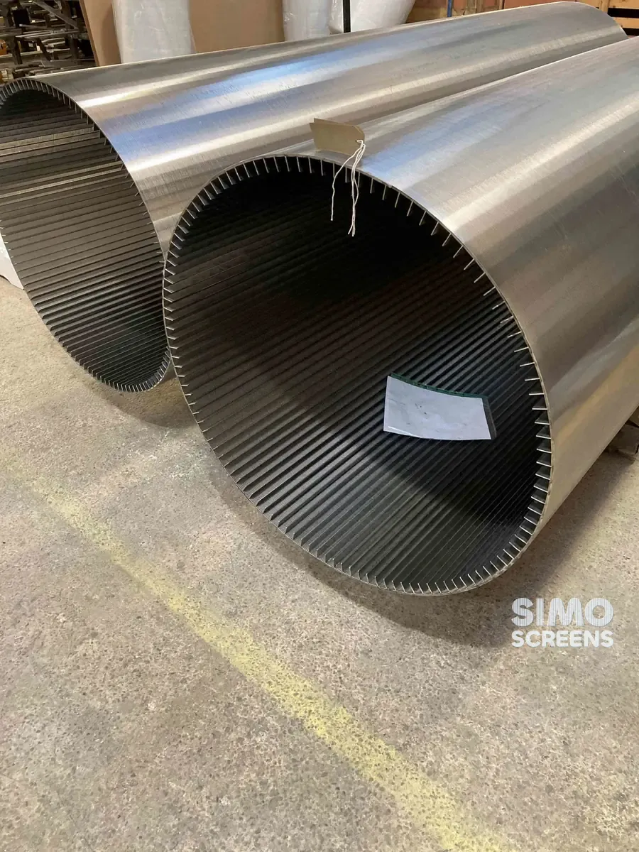
SIMO Screens manufactures tee and single intake screens up to 800 mm diameter for river intakes and cooling water, together with fish and aquaculture screens. Send the design flow, minimum water level, river velocity, debris type and any fish protection condition, and our engineers will size the screen, using CFD to predict pressure drop where the application requires it.