 +91 93730 08466
 Screen tubes and pipes
 Screen cylinders
 Flat panels and false bottoms
 Candle filter elements
 Water well screens
 Header and hub laterals
 Filter nozzles
 Resin traps
 Support grids
 Sieve bend (DSM) screens
 Centrifuge baskets
 Pressure screen baskets
 Screw press screens
 Rotary drum screens
 Passive intake screens
 Coanda intake screens
 Water and wastewater treatment
 Water wells and groundwater
 Sugar and distillery
 Brewing, malting and beverages
 Food processing
 Mining and minerals
 Oil, gas and petrochemicals
 Chemicals, fertilisers and pharma
 Power generation
 Pulp and paper
 Buildings and drainage
The wedge wire screen manufacturing process
A welded wedge wire screen has three elements: V-profile wire, which forms the screening surface; support rods, which carry the load; and a weld at every point where the two cross. The slot between adjacent wires is set mechanically by the winding pitch of the machine, so wedge wire can hold a slot anywhere from 25 microns to 25 mm with consistent accuracy.
Two screens with the same slot and wire on the drawing can still perform differently in service. One holds its slot through years of backwash, while the other loses media because the slot drifts or a weld fails under load. The difference lies in wire accuracy, weld quality, distortion control and inspection, which are the subject of the eight production stages.
| Stage | Purpose |
|---|---|
| Material and traceability | Correct grade, traced from mill to finished screen |
| Profile wire forming | Accurate face width, which controls slot and open area |
| Support rods | Rod size and pitch, which set strength and stiffness |
| Winding and welding | Slot set by pitch, wire fused to every rod |
| Forming | Cylinders, flat panels, curved and internal-profile shapes |
| Fabrication | End rings, flanges, frames and housings |
| Finishing | Heat tint removal and passivation where specified |
| Inspection and documents | Slot, dimensions, welds, marking and MTC |
Swipe sideways to see the whole table.
Step 1: Material and traceability
Production starts with stainless steel or nickel alloy wire and rod of the grade on the order. SIMO Screens works in SS 304, SS 316L, Duplex 2205, Super Duplex 2507, Hastelloy and Monel. Profile wire and support rods are normally of the same grade, so that each weld joins like metals, while flanges and other fittings may differ where the specification allows.
Heat numbers are traceable from the Mill Test Certificate through to the finished screen, and the MTC records the chemistry and mechanical properties of the material supplied. The material selection guide explains how to choose between grades for chlorides, temperature and abrasion.
Step 2: Profile wire forming
Round wire is cold rolled through shaped rolls into the V-profile. Each profile has a flat head, which becomes the screening face, and tapered sides, which form the slot that widens behind the face and gives wedge wire its non-clogging behaviour.
SIMO forms its profile wire in house to SIMO profile codes, each of which fixes the shape, head width and height. Wire is made and stocked by code, and its dimensions are checked with calibrated micrometers before it goes to the welding machine. Profile accuracy matters because a head that varies in width makes the slot vary, even when the winding pitch is exact. The standard range runs from 12SB (1 x 2 mm) to 56SB (5 x 6.5 mm), and custom profiles are made subject to order quantity and frequency.
Step 3: Preparing the support rods
Support rods are cut to length and loaded into a fixture on the welding machine, which holds them parallel and evenly spaced around a circle. The fixture sets the rod pitch, and the rod section sets the strength of the finished screen.
The SIMO rod range runs from light Q23 rods (2 x 3 mm) to deep F253 flat rods (3 x 25 mm), with round rods of 3.15 mm and 3.6 mm diameter for lighter designs. Rod selection is covered in the profile wire and support rod guide.
Step 4: Winding and resistance welding
Winding and welding is the core of the process, and it is where the slot is created.
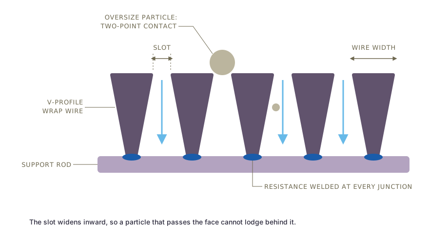
Swipe to see the full drawing.
- The rod cage rotates in the machine.
- The profile wire feeds onto the rods in a continuous spiral, with its flat head facing the flow.
- At each crossing, the wire is resistance welded to the rod.
- The welding head advances along the cage by a fixed distance per turn, which equals wire width plus slot.
SIMO welds on high-frequency transformer resistance welding machines, with seam welding used where the design calls for it. Every wire and rod intersection is resistance welded, so the result is one rigid structure with no loose or crimped joints, which resists thermal cycling and pressure transients up to 300 PSI.
Slot is checked with feeler gauges at welding set-up, during the run and at the end of each screen. Where a physical gauge cannot reach the slot, optical measurement is used. The standard slot tolerance is plus or minus 5 percent of nominal, and it is stated on the drawing.
Axial construction
For axial screens the arrangement is reversed. The support rods are formed into rings, and the profile wires run along the length of the cylinder, each welded to every ring. The spacing between adjacent wires sets the slot, so the fixture that holds the wires governs slot accuracy. Coal centrifuge baskets and similar screens that need slots parallel to the axis are built this way.
Step 5: Forming panels, cylinders and other shapes
The welded cylinder is the starting point for most other shapes.
| Form | How SIMO makes it |
|---|---|
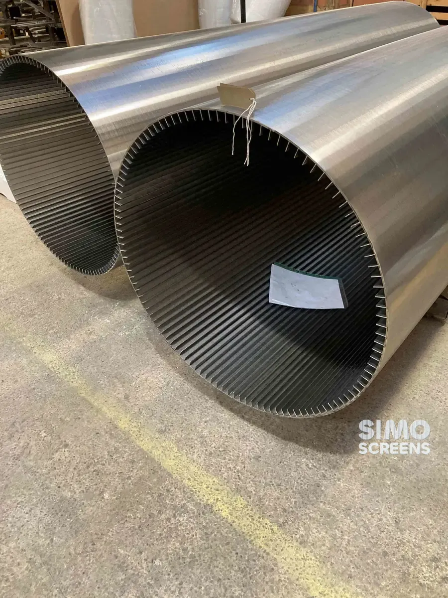
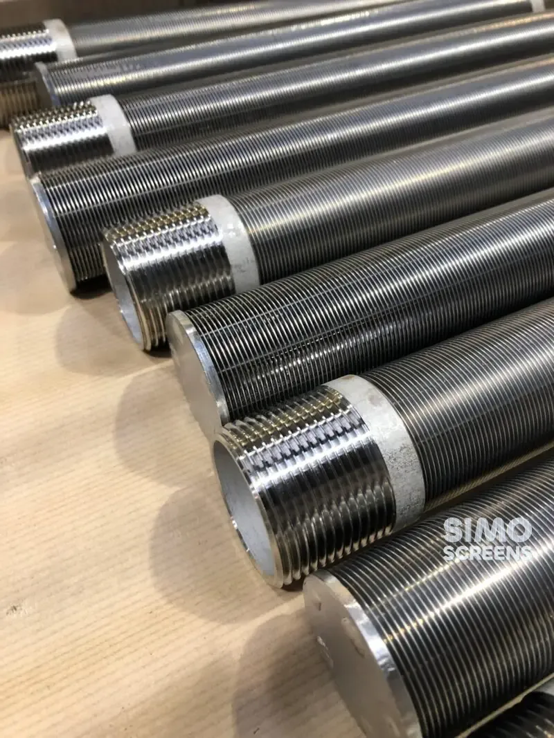
| Cylinders and screen tubes | Used as wound and cut to length |
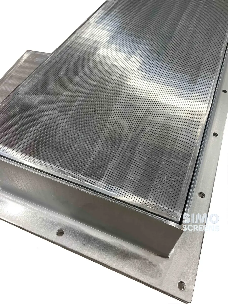
| Flat panels | Usually cut from a welded cylinder along its length, flattened and trimmed |
| Curved panels and sieve bends | Flat panel rolled to the required radius |
| Internal-profile (inside to outside) drums | Flat panel reverse rolled with the slot face inside and seam welded, or wound on an internal-profile machine |
| Conical baskets | Wound on a tapered cage or formed from panels |
| Segmented decks and grids | Panels cut into segments that pass through a manway |
Swipe sideways to see the whole table.
Cylinders and tubes are made from 25 mm to 800 mm diameter in lengths up to 6,000 mm. Single flat panels go up to 2,400 mm wide and 4,000 mm long, and larger decks are engineered as joined panels.
Step 6: Fabrication on the screen
Most screens need more than the wedge wire itself, so SIMO fabricates the parts that fit the screen to the equipment:
- end rings, flanges and threaded or weld-on couplings;
- frames, support bars and edge bands for panels;
- housings, hubs and headers for vessel internals;
- brackets, clamping strips and segment joints;
- rolled and curved sections.
Welding these parts to the screen must not distort the slot, so fixtures and a planned weld sequence keep the screen true while the fittings go on. Fabrication welds are visually inspected, and dye penetrant testing is carried out wherever it is specified.
Step 7: Finishing
Welding leaves heat tint on stainless steel, which lowers corrosion resistance locally at the weld. In chloride-bearing water, hygienic service and other corrosive conditions, the heat tint is normally removed.
The common finishing operations are pickling, which removes heat tint and scale; passivation, which restores the passive chromium oxide film; and electropolishing, which gives a smooth, cleanable surface. SIMO arranges pickling, passivation to ASTM A380 or A967 and electropolishing through approved agencies on request, so the required finish should be stated on the enquiry.
Step 8: Inspection, marking and documents
Every SIMO product goes through full dimensional inspection. The principal checks are summarised below.
| Stage | What is checked | Why it matters |
|---|---|---|
| Incoming material | Grade and chemistry against the MTC | Corrosion resistance and strength |
| Profile wire | Head width and height with calibrated micrometers | Slot accuracy and open area |
| Welding | Slot with feeler gauges at set-up, during the run and at the end | Retention and media loss |
| Fabrication welds | Visual inspection, dye penetrant testing where specified | Structural integrity |
| Finished product | Diameter, length, straightness, flatness, fittings | Fit in the equipment |
| Final report | Minimum, maximum and mean slot | Evidence of slot accuracy |
Swipe sideways to see the whole table.
Each screen is identified by a QR-coded tag carrying the job number, item and slot, and is laser marked on the screen where the client requires it. The Mill Test Certificate is supplied as standard, while the dimensional inspection report, quality assurance plan and positive material identification (through an approved agency) are available on request.
The quality system is certified to ISO 9001:2015, and water well screens are made to IS 8110:2019.
Common defects and how they are prevented
| Defect | What it causes | How it is prevented |
|---|---|---|
| Slot variation along the screen | Media loss at wide spots, blinding at narrow spots | Controlled pitch, consistent profile width, slot checks during the run |
| Weak or missed welds | Wires lift under backwash or vibration and the slot opens | Correct weld settings for the wire and rod, inspection of welds |
| Distortion from fitting welds | Out-of-round cylinders, wavy panels, uneven slot | Fixtures and a planned weld sequence |
| Heat tint left on welds | Local corrosion in chloride water | Pickling and passivation where conditions need it |
| Iron contamination | Rust spots on stainless surfaces | Separate tools and handling for stainless work |
| Wrong profile orientation | Rapid blinding in service | Flow direction marked on the drawing and checked before welding |
Swipe sideways to see the whole table.
A screen that leaves the works with any of these faults will show it in service, usually as media loss or early blinding, so inspection is built into each stage of production.
Supplier evaluation checklist
The following questions help when comparing wedge wire manufacturers:
- Is every wire and rod intersection welded, or are some joints crimped or tack welded?
- How is the slot controlled during winding, and how is it measured afterwards?
- What slot tolerance appears on the drawing?
- Is the material traceable by heat number, with a Mill Test Certificate for the actual heat?
- How is heat tint removed, and is passivation included?
- Will a drawing be supplied for approval before manufacture?
Engineering before production
For custom screens, the work starts at the design desk. SIMO uses CFD for pressure drop prediction and FEA for structural validation of custom designs, and production begins only after the customer approves the drawing.
Related products, tools and engineering support
- Products: wedge wire cylinders and flat wedge wire panels are the two base forms made by this process.
- Tool: the open area calculator shows how slot and wire width set open area.
- Engineering: for designs made to the customer's process data or drawing, see custom engineering.
- Further reading: slot size and open area.